


page 10 of 16 File: SG524_r3eng - April 2017 - Technical note: SG 524
PM 250
SG 524 S
olid
S
tate
M
icrowave
G
enerator
The time it takes by the algorithm to find the best frequency,
with the lowest R/F figure, depends on the distance between
the current and the final frequency, as well as the complexity
of the R/F shape.
In the worst case it should not exceed 10 seconds, but it may
take as little as a second or less.
To shorten the tuning time you may have to select manually a
frequency closer to the expected final frequency (e.g. running
the autotune a first time with the purpose to get this info for
the next trial).
[10]PARAM Threshold R/F: moving the front panel knob,
you can set the threshold of the ratio Rev Power/Forw Power
which has an effect on the Automatic Frequency Tuning, when
this is enabled.
If the current R/F value is below the above “Threshold R/F”
the autotuning has no effect.
The actual R/F figure is computed every 200 mseconds. We
suggest to set a number higher than 10%. With smaller figure,
and a cavity with low Q factor, the system may not be able to
reach a fixed frequency.
[11]PARAM Reverse Power Max: moving the front panel
knob, you can set the limit of the reverse power before the
alarm. The unit can bear a total reflection condition for a
certain time, but be careful: in case of heavy standing wave,
the generator may be overloaded with the sum of both forward
and reverse power, and parts of the circuit on the final power
combiner, as well as the coaxial socket may be damaged.
Software release
Release no
.
PSU version
Note
2.00
v.2 “Display”
Compatible with Front
Panel Vers. 7.20
2.01
v.2 “Display”
Update of internal para-
meters:max rev thre-
shold 300W
2.02
v.2 “Display”
Update of the Alarms
codes’ table
2.03
v.2 “Display”
Update of the MOS cur-
rents’ alarms
2.04
v.2 “Display”
& v. 1 “Field-
Bus”
Update of Bus communi-
cation protocol
2.10
v. 2 & v. 1
New CPU
Note*: the last alarm occured is permanently stored
by the CPU , even in absence of main line, and can
be verified using the Front Panel software (vers. 7.20
and over)
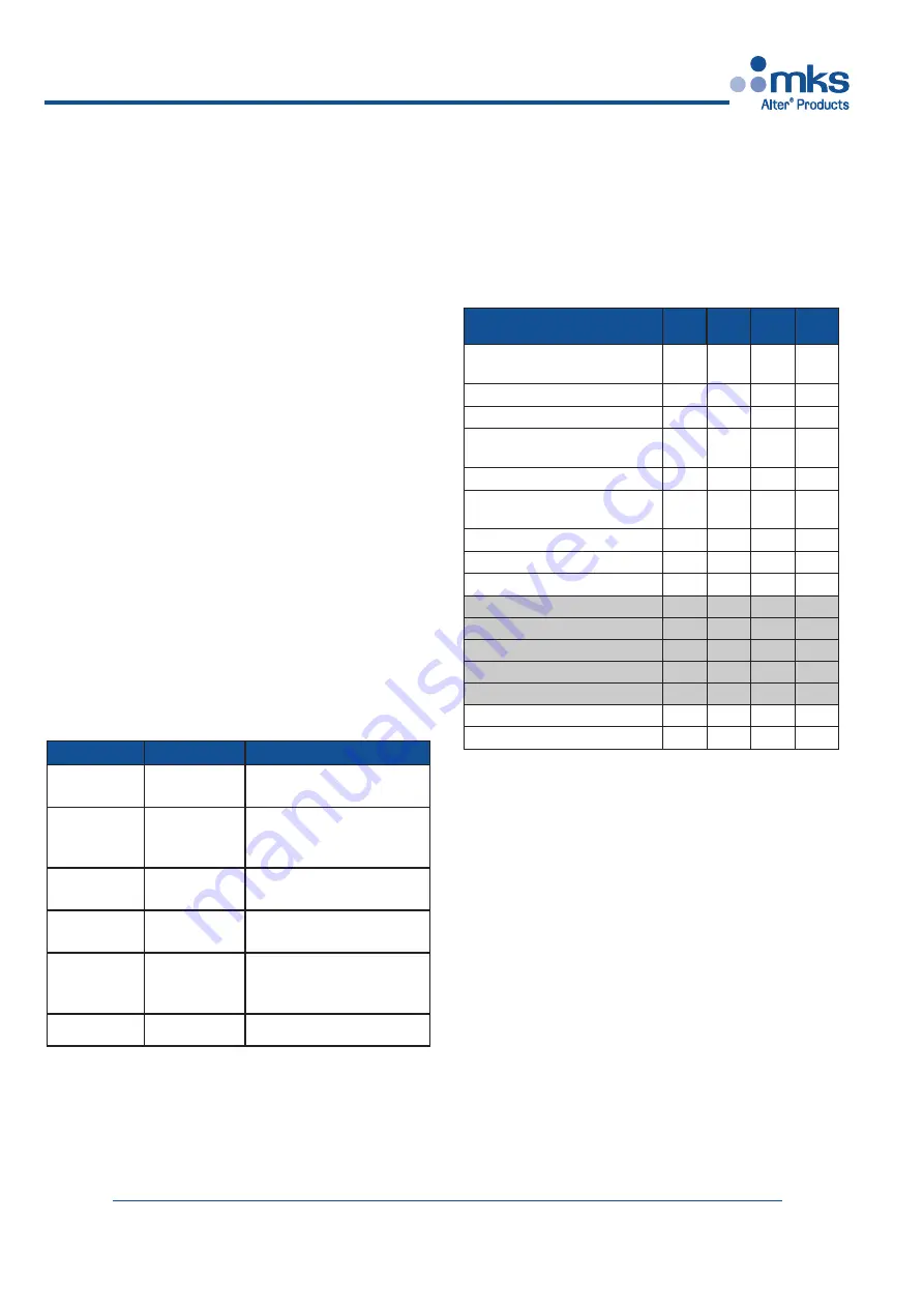
Description
BIT 3
[22]
BIT 2
[ 9]
BIT 1
[21]
BIT 0
[ 8]
Power Module
Overtemperature
0
0
0
0
Reverse Power Alarm
0
0
0
1
Power Module Alarm (PLL)
0
0
1
0
Internal Safety Relay
Malfunction
0
0
1
1
Power Supply Undervoltage
0
1
0
0
AC/DC Power Supply
Overtemperature
0
1
0
1
Internal Overload (M1)
0
1
1
0
Internal overload (M2)
0
1
1
1
Interlock Alarm
1
0
0
0
not implemented
1
0
0
1
not implemented
1
0
1
0
not implemented
1
0
1
1
not implemented
1
1
0
0
not implemented
1
1
0
1
Communication Interrupted
1
1
1
0
Bus Communication Failed
1
1
1
1
Table of Alarm Codes
The alarms are also coded with a number that is emitted on the
4 bit outputs provided on CONN #5 (see the relevant schema-
tic at page 12).
The following is the table with the indication of the codes.