background image

Chapter Five:  Repair 

General Information


21 

Chapter Five:  Repair 

General Information 

If the 248 valve instrument fails to operate properly upon receipt, check for shipping damage, 
and check the cables for proper continuity.  Any damage should be reported to the carrier and 
MKS Instruments immediately.  If it is necessary to return the unit to MKS, obtain an RMA 
number (Return Material Authorization Number) from a MKS Service Center before shipping.  
Please refer to the inside back cover of this manual for a list of MKS Calibration and Service 
Centers. 

Warning


All returns to MKS Instruments must be free of harmful, 
corrosive, radioactive, or toxic materials.


Summary of Contents for 248A

Page 1: ...service in house repair center WE BUY USED EQUIPMENT Sell your excess underutilized and idle used equipment We also offer credit for buy backs and trade ins www artisantg com WeBuyEquipment REMOTE IN...

Page 2: ...107428 P1 Rev L 8 06 MKS Type 248A B C Control Valve...

Page 3: ...n storage or retrieval system except as may be expressly permitted in writing by MKS Instruments Inc Cajon and VCR are registered trademarks of Cajon Company Macedonia OH Kalrez and Viton are register...

Page 4: ...Interface Cables 8 Generic Shielded Cable Description 8 Setup 10 Dimensions 10 Mounting Instructions 11 Cables 11 Chapter Three Operation 13 General Information 13 Chapter Four Maintenance 15 General...

Page 5: ...Table of Contents iv Index 27...

Page 6: ...res Figure 1 Preferred Method To Connect a Shielded Cable 9 Figure 2 Alternate Method To Connect a Shielded Cable 9 Figure 3 Dimensions of a Type 248 Control Valve 10 Figure 4 Typical Valve Assembly E...

Page 7: ...List of Figures and Tables vi...

Page 8: ...injury If necessary remove the MFC from the process equipment to adjust the valve Questions concerning the safe handling of toxic or hazardous gases may be answered by consulting your corporate polic...

Page 9: ...mpatible with the intended use of the instrument Assemble and tighten fittings according to manufacturer s directions CHECK FOR LEAK TIGHT FITTINGS Before proceeding to instrument setup carefully chec...

Page 10: ...ctly performed or adhered to could result in injury to personnel Caution The CAUTION sign denotes a hazard It calls attention to an operating procedure practice or the like which if not correctly perf...

Page 11: ...Safety Procedures and Precautions 4 This page intentionally left blank...

Page 12: ...placed without special tools Adjustment may be required to eliminate leakage across the valve resulting from normal operational wear Replacement is required when wear has become excessive or when it b...

Page 13: ...strument to MKS should any repair be needed Appendix A Product Specifications lists the specifications of the instrument Appendix B Model Code Explanation describes the instrument s ordering code Cust...

Page 14: ...orization Number from the MKS Service Center before shipping Please refer to the inside of the back cover of this manual for a list of MKS Calibration and Service Centers Unpacking Checklist Standard...

Page 15: ...al wires exit 3 With very few exceptions the connector s must make good contact to the device s case ground Good contact is about 0 01 ohms and the ground should surround all wires Contact to ground a...

Page 16: ...asher Transducer Housing Optional Plastic or Metal Cable Clamp For Physical Strain Relief Figure 1 Preferred Method To Connect a Shielded Cable Example 2 Alternate Method To Connect Cable shown on a t...

Page 17: ...tup Dimensions Note All dimensions are listed in inches with millimeters referenced in parentheses Table 1 A B in mm in mm 4 VCR 3 37 85 6 3 38 85 9 4 VCO 3 05 77 5 1 4 Swagelok 2 76 70 1 Figure 3 Dim...

Page 18: ...couple the 248 valve with the minimum practical length of straight tubing to the upstream flow sensor to achieve stable flow control Cables To connect the 248 valve to a Type 250D E or 1250 controlle...

Page 19: ...Setup Chapter Two Installation 12 This page intentionally left blank...
Page 20: ...ing the inlet pressure up to the maximum allowed This extends the maximum flow control range from approximately 3X 10K sccm range to 250X 10 sccm range Decreasing the outlet pressure increases the flo...

Page 21: ...General Information Chapter Three Operation 14 This page intentionally left blank...

Page 22: ...o Figure 4 page 16 as needed Note Turn the orifice 5 to 10 at a time each time observing a change in leakage Turn the orifice an additional 10 to 15 beyond the threshold of acceptable leakage Excessiv...

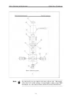
Page 23: ...apter Four Maintenance 16 Note The drawing above is provided for reference purposes only Disassembly of the valve will void its warranty For maintenance please contact MKS Instruments Inc and obtain a...

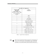
Page 24: ...th O rings see 10 6 Orifice Assembly without O rings 7 Swagelok Fitting 8 Socket Head Screw 8 32 x 0 50 9 Hex Nut 7 16 14 10 O Ring Viton Size 2 016 11 O Ring Viton Size 2 009 12 O Ring Viton Size 3 9...

Page 25: ...Note the position at removal Replace the parts if the cover is damaged or the coil is an open circuit 3 Remove the four 8 32 screws holding the Collar to the Body 4 Remove the Collar and Center Shaft...

Page 26: ...nstall a new O ring furnished with the replacement Armature Plug Assembly on the Center Shaft Assembly and install this assembly into the Body and onto the main spring 5 Install the collar and the fou...

Page 27: ...Assembly Chapter Four Maintenance 20 This page intentionally left blank...

Page 28: ...amage should be reported to the carrier and MKS Instruments immediately If it is necessary to return the unit to MKS obtain an RMA number Return Material Authorization Number from a MKS Service Center...

Page 29: ...General Information Chapter Five Repair 22 This page intentionally left blank...

Page 30: ...mum Inlet Pressure2 150 psig Maximum Throughtput 1 atmosphere at inlet 50 slm maximum valve range configuration Minimum Controllable Flow Rate 0 2 F S 100 sccm 0 1 F S 100 sccm to 10 000 sccm 2 F S fo...

Page 31: ...General Information Specifications 24 This page intentionally left blank...

Page 32: ...s follows XXXXX Y Z where Type Number Fittings Seals Y Z Full Scale Range XXXXX Type Number This designates the model number of the instrument 0248A Full Scale Range XXXXX The full scale range is indi...

Page 33: ...Code Swagelok tube standard S Cajon 4 VCR male optional R Cajon 4 VCO male optional G Seals Z Four types of seals are available designated by a single letter code Ordering Code Viton standard V Neopre...

Page 34: ...s 8 M Maintenance cleaning 18 disassembly 18 inspection 18 orifice 15 Manual organization 6 Messages definitions of 3 Model code 25 Mounting instructions 11 R Range 25 Returning the product 6 7 21 S S...

Page 35: ...service in house repair center WE BUY USED EQUIPMENT Sell your excess underutilized and idle used equipment We also offer credit for buy backs and trade ins www artisantg com WeBuyEquipment REMOTE IN...

Reviews: