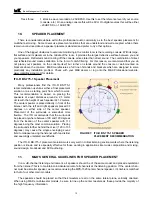
The speakers should be placed so that the tweeters are
directly in line with the listener’s ears, that is, on-axis. (M&K pow-
ered speakers have a red LED recessed into the front baffle. The
listener will know when his speakers are on-axis when he can see
this LED. If this LED is not visible, either the speaker is turned-off
or the speakers are aimed off-axis).
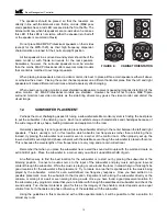
Do not place M&K MPS Professional speakers on their sides
(except for the MPS-1520), as their high frequency dispersion
characteristics are tuned for their normal upright position.
All five speakers in a surround sound system should be of the
same model or with Tripole surrounds for the rear speakers.
Sometimes, however, the surround speakers must be smaller
than the mains. M&K Professional offers several smaller models
that are timbre matched to our larger speakers.
When placing loudspeakers around a video monitor, it is best to place all three main speakers either all above
or all below the screen. Placing the center channel speaker on a different horizontal plane from the left and right
speakers will create different arrival times and will adversely effect imaging.
When used near a video monitor, select shielded loudspeakers to prevent gaussing (magntic distortion) of the
video monitor. All M&K Professional monitors are shielded. However, be careful not to place M&K Tripole
surround monitors near video monitors as the side-firing drivers may gauss the video monitor and distort the
visual image.
12.
SUBWOOFER PLACEMENT
Perhaps the most challenging aspect of tuning a subwoofer/satellite monitor system is finding the best place
to put the subwoofer in the listening room. Each room exhibits unique characteristics and challenges because of
the wide range of size, shape, building materials and equipment in the room.
Generally speaking, it is not a good idea to place the subwoofer directly in the center between the left and right
speakers. There’s usually a null in this location which absorbs low frequencies rather than reinforcing them.
Instead, try placing the subwoofer near a wall or even in a corner of the control room. When properly set up, the
low end will still sound tight and phase-coherent with the satellites even though the subwoofer is placed off-center.
This is because the wavelengths of low frequencies are very long and are omni-directional.
Remember that when you place the subwoofer near a wall the sound will couple with the wall and create an
extra 3dB of gain. Place the subwoofer in a corner and you will pick up additional 3dB of gain.
An effective way to find the best location for the subwoofer is to start out by placing the subwoofer at the
listening position. Connect an audio source to the input of the subwoofer and play music with good low-end
content through the subwoofer. While the music is playing, move around the room in areas that you think might be
good locations for the subwoofer’s final placement. Try to locate an area that responds well to the music being
played by the subwoofer. Listen for even, well-defined, low frequency response. Once you have settled on a
possible placement, move the subwoofer to that location. Experiment with aiming the subwoofer directly at the
console, or aiming it at a wall or even aiming it along a wall. Once you have found a good placement solution for
the subwoofer, play program material that you are familiar with through the satellites and subwoofer and check the
sound quality. Two-channel material is good for this as the imagery of the phantom center depends upon equal
volume from both channels and phase coherency of the satellites with the subwoofer.
Using the guidelines in this manual and with a little experimentation, it will be possible to find a solution for
almost any room.
Bass Management Controller
13
FIGURE 8:
CABINET ORIENTATION


