


CAUTION
- Connect the power cord to
a power source with safety
equipment in order to prevent
the risk of an electric shock.
- Make sure to use the
dedicated power cord with
"MIZUHO" logo.
- Make sure that the connector
of the power source is not
intruded in by fluid and is not
dusty before plugging the
power cord into the connector
of the power source.
- Pull out the power cord from
the medical grade wall outlet
to cut the power supply
completely.
- If the battery deteriorates, it
will not be available for the
operating table when AC
power is not supplied due to
power outage etc.
24
4
Operation
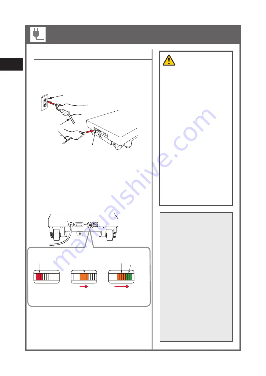
Battery charging
2. When turn on the power switch, battery charging starts.
While charging, the battery indicator sequentially
flashes orange.
1. To start charging, insert the power cord into the
power connector and into a medical grade wall
outlet.
medical grade wall outlet
power cord
connector of
the power source
3. When the battery indicator sequentially flashes
orange and green, charging is completed.
NOTE
- When you first purchase the
product or have not used it
for a long time, make sure to
charge the battery before use.
Battery will get discharged
naturally even when the table
is not used.
- If the battery lamp on the
control unit flashes after using
the operating table or the
battery indicator on the lower
part of the operating table
shows empty (red) when
using, charge the battery
immediately. When the
battery is discharged, only the
AC power is available and will
not be able to use the battery
power.
BATTERY INDICATOR
Charging in progress
(sequentially flashes
orange)
Charging complete
(sequentially flashes
orange and green)
Needs charging
(lit red)
E
F
E
F
E
F
Orange
light up in order
Red
light up
Orange and
Green
light up in order
Installation and battery charging
Summary of Contents for MOT-VS600
Page 2: ......
Page 4: ......
Page 5: ...1 Introduction 1 Introduction ...
Page 6: ...2 1 Introduction ...
Page 10: ...6 1 Introduction ...
Page 11: ...2 Before use 2 Before use ...
Page 19: ...3 Component identification 3 Component identification ...
Page 24: ...20 3 Component identification ...
Page 60: ...56 4 Operation ...
Page 61: ...5 Maintenance and inspection 5 Maintenance and inspection ...
Page 64: ...60 5 Maintenance and inspection ...
Page 65: ...6 Specifications 6 Specifications ...
Page 69: ...7 Troubleshooting 7 Troubleshooting ...
Page 71: ...8 Before contacting for repairs 8 Before contacting for repairs ...


