background image

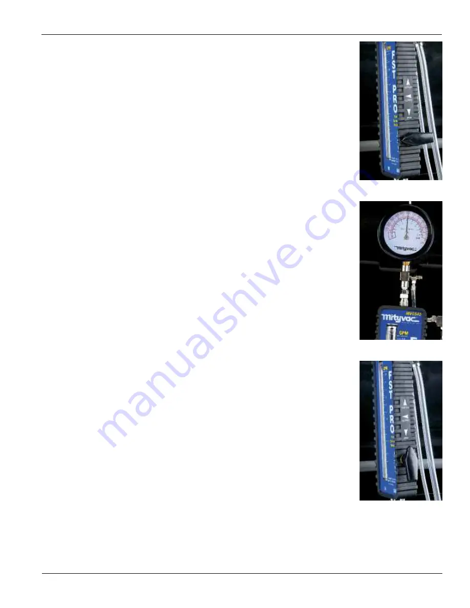
Fig. 51

Fig. 52

Fig. 53

After connecting the FST, it is normal to have air trapped in the
fuel lines and flowmeter. Cycling the ignition switch (or cranking
the engine briefly) with the flow control valve in the BYPASS posi-
tion can help purge air from the system. Once fuel fills the
flowmeter and flows through the bypass hose, return the valve to
the OPEN position. The bypass hose must be routed and secured
into an approved fuel container before operating the flow control
valve in BYPASS mode.

To perform an accurate diagnosis using the FST, the car must be
running in order to provide the correct operating voltage to the
fuel pump. Testing the fuel system by activating the fuel pump
using a scan tool will cause the fuel pump to severely under-per-
form.

3. Note the fuel system pressure indicated on the pressure gauge,

and compare it with the vehicle manufacturer’s specification
(Fig. 51).

Typical electronic fuel injection system pressures range from 30 to
60 PSI (205 to 410 kpa) depending on the vehicle being tested.
Always use the recommended vehicle service information, proce-
dures, and pressure specifications for the specific vehicle being
tested.

NOTE:

The flow of fuel passing through the tester represents only

what the engine is using at idle. It will be negligible and most likely
not even register on the flowmeter.

Pressure Demand (Dead-head) Test

4. With the car idling, rotate the flow control valve on the side of the

flowmeter towards the 90° CLOSED position (Fig. 52).

Rotating the valve to CLOSED creates a restriction to the flow of
fuel through the tester. Watch the pressure gauge, as the valve is
rotated, the pressure should increase. Note the pressure when the
valve is fully closed. A good fuel pump should be capable of pro-
ducing pressure 50% to 100% higher than the rating of the fuel
system.

Caution:

Never rotate the valve to the closed position for longer

than a brief instant. This is referred to as “dead-heading” the
pump, and can cause serious damage to the fuel system or
pump.

5. After noting the peak pressure, rotate the flow control valve back

to the OPEN position, and proceed to the flow demand test.

Flow Demand Test

6. With the car idling, rotate the flow control valve past the CLOSED

position to the BYPASS position pointing up (Fig. 53).

With the valve in the BYPASS position, the flow of fuel is routed
through the bypass port located above the valve, through the
bypass hose, and into the reservoir. All restriction to the flow of
fuel is removed. This allows the pump to output its maximum flow,
the value of which can be read on the flowmeter. The free flow
output of a typical fuel pump is between .7 and 1.0 GPM (2.5 and
4 LPM).

NOTE:

Turning the valve to the full BYPASS position will prevent

fuel from flowing to the engine. If left in the BYPASS position for
too long, the engine will stall. If this happens, simply return the
valve to the OPEN position and restart the vehicle.

7. After noting the peak pressure, return the flow control valve to the

OPEN position, and proceed to the capability test.

Peak Demand Test

8. Note the vehicle’s engine size and maximum engine speed (RPM).

Refer to the Maximum Engine Fuel Volume Requirements table
(Appendix A), and use the size and speed values to determine the
maximum fuel volume requirement of the engine.

Page Number - 29

Summary of Contents for MV5545

Page 1: ...USER S MANUAL FST PRO FUEL SYSTEM TESTER MODEL MV5545...

Page 2: ...ly Regulated 15 In tank Filtering In tank Return 15 External Filtering In tank Return 15 External Filtering External Return 15 Electronically Regulated 16 Identifying Fuel Delivery Systems 16 Fuel Sys...

Page 3: ...void burns by remaining cautious of engine parts that may become hot when the engine is running Never leave a vehicle unattended while testing Check and secure all fuel system connections before start...

Page 4: ...rs Minute includes front and back plate 824142 Flowmeter Faceplates Gallons Minute includes front and back plate 824172 Quick connect Replacement Clips Qty 6 824179 Storage Case 824141 824149 824148 8...

Page 5: ...w Control Valve Knob 5 824174 Flowmeter Inlet Outlet Connector Qty 2 6 824146 Flow Control Valve 7 824145 Flowmeter Seal Kit 824183 Wing Style Hose Clamp Qty 4 824181 Flowmeter Boot 824180 Adapter O R...

Page 6: ...5 16 or 3 8 rubber to steel hose connection MVA505 16 1 4 Flex Hose Adapter Vehicles with 1 4 rubber to steel hose connection 16A 5 16 Flex Hose Adapter Vehicles with 5 16 rubber to steel hose connect...

Page 7: ...ec MVA521 4A 4B 3 8 Flare Nut Adapter Carbureted early fuel injected systems MVA522 6A 6B 5 16 Flare Nut Adapter Carbureted early fuel injected systems MVA523 5A 5B 3 8 Spring Lock Adapter Ford fuel i...

Page 8: ...e held securely by the lip of the rubber boot that surrounds the flowmeter For accuracy they pilot on the caps that seal the top and bottom of the flowtube To remove the faceplates simply peel back th...

Page 9: ...he first time it is encountered A banjo connection consists of a round hollowed out banjo connector with two flat sides A hollow bolt with a cross hole passes through the banjo connector and threads i...

Page 10: ...ed Fig 16 5 Follow normal testing procedures Proper Use Care and Servicing With proper care and maintenance the FST Pro will provide years of accurate reliable service The FST is designed for use in t...

Page 11: ...fuel delivery system preventing the engine from receiving the optimal fuel pressure and flow it requires to perform at peak efficiency and performance Assist the technician in accurately pinpointing...

Page 12: ...meet maximum engine requirements is to test it under the engine s most demanding conditions Using patented technology the FST Pro is the only tester capable of simulating demand on a vehicle s fuel de...

Page 13: ...be noted On a return system or electronically regulated returnless system the pressure value should be higher than the manufacturer s specification On a mechanically regulated returnless system the p...

Page 14: ...the way back to the fuel pump This backpressure is the pressure at which fuel is delivered to the injectors and what is referred to by the vehicle manufacturer s specification for proper fuel pressur...

Page 15: ...g the exact cause of the malfunction may be irrelevant because the pump filter and pressure regulator are all part of a module assembly that must be replaced as a complete unit In tank Filtering In ta...

Page 16: ...h feeding the injectors in one of the banks There will be a crossover between the rails to allow fuel to flow from one side to the other Fuel rails vary in appearance from simple round tubes to square...

Page 17: ...rvice manual should document this in their fuel system diagnostic procedure Fuel pumps fail or fail to perform due to high mileage contaminated fuel or electrical problems While there is no fix for we...

Page 18: ...tant pressure differential across the fuel injectors This means that fuel rail pressure will vary depending on manifold vacuum At idle manifold vacuum is high This causes the regulator to pass more fu...

Page 19: ...d Asian manufactured cars and light trucks In most cases making an inline connection with the FST requires two adapters one to connect the fuel line from the fuel tank to the FST inlet and the second...

Page 20: ...Follow the vehicle manufacturer s recommended procedure to relieve the pressure from the vehicle fuel delivery system 3 Locate the fuel supply line to the engine s fuel rail and select the best locat...

Page 21: ...clear pressure relief and bypass hoses into an approved gasoline container Route the flowmeter inlet and outlet fuel hoses away from rotating engine components belts fans and hot exhaust components R...

Page 22: ...p If the fuel pump does not operate refer to the vehicle service information for electrical diagnosis and repair of the fuel pump and associated controls After connecting the FST it is normal to have...

Page 23: ...the flow of fuel is routed through the bypass port located above the valve through the bypass hose and into the reservoir All restriction to the flow of fuel is removed This allows the pump to output...

Page 24: ...inpoint a malfunc tion Blocked Inline Fuel Filter If the inline filter is clean pressure and flow in Zones 1 and 2 should be equal A clogged filter will cause the pressure to increase in Zone 1 and th...

Page 25: ...r restrict the flow Follow the vehicle manufacturer s procedure for locating and repairing the cause of the vacuum loss and retest If vacuum is normal connect the FST in Zone 3 preferably right after...

Page 26: ...e fuel pump Testing the fuel system by activating the fuel pump using a scan tool will cause the fuel pump to severely under per form 3 If the vehicle utilizes a multiple speed fuel pump use a scanner...

Page 27: ...ues to expe rience symptoms of a fuel delivery malfunction it could be caused by contaminated fuel faulty fuel injector s or an intermittent component malfunction such as a sticking pressure regulator...

Page 28: ...cate a pump problem If the FST indicates a pump is under performing be sure to verify that the vehicle does not use a multiple speed pump see Fuel System Components Fuel Pumps To properly test a fuel...

Page 29: ...of fuel through the tester Watch the pressure gauge as the valve is rotated the pressure should increase Note the pressure when the valve is fully closed A good fuel pump should be capable of pro duc...

Page 30: ...and the diagnostic chart clearly pinpoints the cause follow the vehicle manufacturer s repair procedures to correct the malfunction After performing the repairs re test the fuel delivery system with t...

Page 31: ...as they pass through the flowmeter Air bubbles can also be caused by a bad swirl pot or leaking fuel pickup line in the tank which allow air to be sucked into the fuel pump Performing flow demand tes...

Page 32: ...inimal release of fuel Follow the procedures below and always observe the safety precautions listed in the front of this manu al Carefully read the warning below concerning disconnecting from a hot re...

Page 33: ...ut starting the engine will run the fuel pump briefly to prime the fuel system on most vehicles Always check fuel line connections to ensure they are securely fastened and do not leak 7 Place the disc...

Page 34: ...21 0 29 0 36 0 43 0 50 0 57 5 0 305 0 22 0 30 0 37 0 45 0 52 0 59 5 2 317 0 23 0 31 0 39 0 46 0 54 0 62 5 4 330 0 24 0 32 0 40 0 48 0 56 0 64 5 6 342 0 25 0 33 0 42 0 50 0 58 0 66 5 8 354 0 26 0 35 0...

Page 35: ...79 1 10 1 36 1 63 1 89 2 16 5 0 305 0 83 1 14 1 40 1 70 1 97 2 23 5 2 317 0 87 1 17 1 48 1 74 2 04 2 35 5 4 330 0 91 1 21 1 51 1 82 2 12 2 42 5 6 342 0 95 1 25 1 59 1 89 2 20 2 50 5 8 354 0 98 1 32 1...

Page 36: ...M 2 5 LPM Normal 50 to 100 higher than spec Normal 7 to 1 0 GPM 2 5 to 4 0 LPM Under restricting pressure regulator 4 High Low Less than maxi mum fuel vol ume require ment Normal 50 to 100 higher than...

Page 37: ...rmal replace the pressure regulator Scenario 4 Diagnosis High pressure and low flow at idle indicates too much restriction in the path of the fuel as it returns from the fuel rail to the fuel tank The...

Page 38: ...re regulator 4 High Normal 7 to 1 0 GPM 2 5 to 4 0 LPM High Above manufacturer s specification Over restricting pressure regulator 5 Low Low Less than 7 GPM 2 5 LPM Low Greater than 10 below manufactu...

Page 39: ...el tank and inline filter and retest If peak flow is normal replace inline filter If flow is still low replace inlet screen sock Scenario 3 Diagnosis Low idle and capability pressure combined with nor...

Page 40: ...to 4 0 LPM Fuel system is operating normally 2 Normal Low Greater than 10 below idle pressure Normal 50 to 100 higher than spec Low Less than 7 GPM 2 5 LPM Blocked fuel filter inlet strainer or pinche...

Page 41: ...such as wide open throttle Additional Action Inspect the fuel supply line for damage Connect FST between fuel tank and inline filter and retest If the peak flow and capability pressure are normal rep...

Reviews: