Fig. 25
Fig. 24
Fig. 23
Page Number - 15
Returnless fuel systems (mechanically regulated) were pioneered by
Chrysler in the mid-90s. Since that date, other car manufacturers
have been implementing returnless systems onto their cars. Now
returnless systems are common on most all new cars and light trucks.
Mechanically Regulated
In the case of mechanically regulated returnless systems, the term
“returnless” can be misleading. Like a return system, the fuel pump
operates continuously, producing an uncontrolled output. Since the
engine will only use a portion of the total pump output, the excess
fuel must still be returned. This is done either in the tank, or the fuel
is routed just outside the tank for filtering, and then returned.
Mechanically regulated systems utilize a spring operated pressure
regulator mounted in the tank as part of the pump module. The regu-
lator is very similar to those used in return systems, except it is not
vacuum- or pressure-modulated. Fuel pressure in returnless systems
is typically higher than return systems to compensate for the lack of
modulation, and to help prevent the fuel from boiling in the fuel rail.
Mechanically regulated returnless fuel systems employ one of three
basic concepts to filter the fuel and accommodate the excess output
of the pump. All three methods utilize a fuel pump module with
built-in pressure regulator. The FST is very capable of diagnosing
a malfunction of any of the three variations. However the type of
return/filtration method employed has a significant impact on the
FST’s capability to pinpoint the malfunction. Refer to the Testing and
Diagnostics section later in this manual for the proper application of
the FST in diagnosing each system. In some cases, pinpointing the
exact cause of the malfunction may be irrelevant because the pump,
filter, and pressure regulator are all part of a module assembly that
must be replaced as a complete unit.
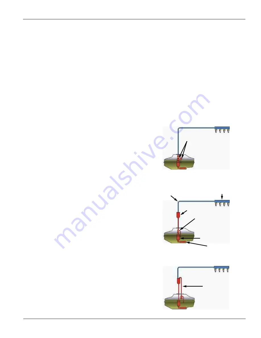
In-tank Filtering/In-tank Return
This method involves filtering and returning the excess fuel without it
leaving the tank (Fig. 23). Both pressure regulator and filter are part of
the fuel pump module. Filtering is accomplished in one of three ways:
•
A pre-pump filter is used to filter the fuel before it enters the pump.
•
The filter is located after the pressure regulator, where it filters the
unused fuel before mixing it back into the fuel reserve.
•
The filter is located in the pump module, between the pump and
the regulator.
Some manufacturers have designed in-tank filter/regulator systems
that use some variation or combination of these three concepts to
produce what they consider to be the most effective system. In cases
involving in-tank filtering and return, all of the control components are
included as part of the pump module assembly, and are most likely
replaced as a complete unit.
External Filtering/In-tank Return
This system of fuel filtration and return uses a pressure regulator on
the pump module to regulate fuel pressure and return unused fuel
before it leaves the tank. The main filtration is handled by an inline
filter mounted externally between the tank and the fuel rail (Fig. 24).
External Filtering/External Return
In this type of filtering/return system, the fuel is pumped out of the
tank to an external filter mounted on or near the tank (Fig. 25). The fil-
ter serves as a sort of manifold, with a single fuel supply line running
into one end of the filter, and two fuel lines exiting the filter. One of the
exiting lines supplies fuel to the engine, while the other returns the
unused fuel to the regulator and the tank.
Fuel Filter
Fuel Filter
Pressure Regulator
Fuel Pump
Inlet Strainer/Sock
Fuel Return
Fuel Rail
Fuel Supply Line


