background image

57

Appendix A: Bypassing the V-Chip Lock

Appendix A: Bypassing the V-Chip Lock

Bypassing the V-Chip Lock

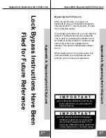
After you set the lock, you need your
passcode to view a V-Chip locked program,
view the locked TV, cancel the lock, or enter
the V-Chip lock menus.

If you forget your passcode, you can view the
locked TV without entering your passcode.
This is done by pressing the number 9 and
QV buttons on the remote TV control at the
same time, when your password is re-
quested. This process temporarily unlocks
the TV.

When entering the V-Chip Lock menu, this
process deletes your old passcode and
prompts you to enter a new passcode.

Appendix 

A: Bypassing the V

-Chip Lock

Lock Bypass Instructions Have Been

 Filed for Future Reference

Appendix 

A: Bypassing the V

-Chip Lock

57

Cut along the dotted line and file by-

pass instructions in a safe place for
future reference.

When using this method for changing or

deleting your passcode, you must use the
remote control included with this TV. You
cannot use a Mitsubishi remote control from
another component or a “universal” remote.

Summary of Contents for WD-65000

Page 1: ...Digital Light Projection Television Model WD 65000 visit our website at www mitsubishi tv com TM ...

Page 2: ...e will not occur in a particular installation If this equipment does cause harmful interference to radio or television reception which can be determined by turning the equip ment off and on the user is encouraged to try to correct the interference by one or more of the following meas ures Reorient or relocate the receiving antenna Increase the separation between the equipment and the receiver Conn...

Page 3: ...ock Menu 43 A V Setting Descriptions 44 45 Remote Control Functions 48 55 Overview 48 Care and Operation 49 Channel Selection 50 Sleep Timer 50 System 4 Home Theater IR Control 51 Special Functions 52 Operation of PIP and POP 52 53 Display Formats 54 55 Appendix A Bypassing the V Chip Lock 57 Appendix B High Definition Inputs Connection Compatibility 59 Appendix C Remote Control Programing Codes 6...

Page 4: ...ps excessive force and uneven surfaces may cause the appli ance and cart combination to overturn 7 Ventilation Slots and openings in the cabinet are provided for ventilation and to ensure reliable operation of the TV and to protect it from overheating Do not block these openings or allow them to be obstructed by placing the TV on a bed sofa rug or other similar surface Nor should it be placed over...

Page 5: ...ce Unplug the TV from the wall outlet and refer servicing to qualified service personnel under the following conditions a When the power supply cord or plug is damaged b If liquid has been spilled or objects have fallen into the TV c If the TV has been exposed to rain or water d If the TV does not operate normally by following the operating instructions adjust only those controls that are covered ...

Page 6: ...your television call Consumer Relations at 800 332 2119 or email us at MDEAservice bigscreen mea com To order replacement or additional remote controls or owner s guides call 800 553 7278 or visit our website at www mitsubishi tv com ...

Page 7: ...7 Thank You Thank You Letter 8 Unpacking Your New TV 9 Special Features 0 ...

Page 8: ...f sources To that end Mitsubishi went a step beyond the Diamond Series and developed the WD 650001 We selected DLP Technology one of the most significant advances in projection TV displays since the introduction of the CRT DLP Technology has the im pressive ability to display both television pictures and computer images with a level of detail color and clarity that has never before been offered fo...

Page 9: ...ges with a level of detail color and clarity that has never before been offered for the home theater The advanced circuitry has the ability to accept Conventional video 480i Progressive scan video 480p Both 1080i and 720p HDTV images VGA S VGA and XGAcomputer graphics HD Upgradeable With the use of an optional DTV receiver like the Mitsubishi SR HD500 or similar model your Mitsubishi bigscreen can...

Page 10: ...ected DLP Technology one of the most significant advances in projectionTV displays since the introduction of the CRT DLP Technology has the impressive ability to display both television pictures and computer images with a level of detail color and clarity that has never before been offered for the home theater 1With the addition of an HDTV digital receiver all Mitsubishi HD Upgradeables will offer...

Page 11: ...nections Affect PIP and POP 14 System 4 Home Theater IR Control 14 15 Connecting to Your New Mitsubishi Bigscreen Antenna or Wall Outlet Cable 16 Cable Box 16 VCR 17 Audio Receiver 18 DVD Player 19 S Video Device 19 DTV Receiver 20 21 Computer 22 System 4 Home Theater IR Control 22 ...

Page 12: ... terminal on the front panel is possible for a component connected to either PC 2 or Input 5 Front control Panel Functions STATUS POWER POWER VOLUME ADJUST CHANNEL ENTER ENTER ADJUST MENU MENU A V RESET CANCEL INPUT 1 2 3 S VIDEO VIDEO PC 2 INPUT 5 L AUDIO R 4 5 6 Steady green STATUS POWER CONDITION NOTES Under normal operation Abnormal operation notice The POWER is ON Lamp start up for 30 seconds...

Page 13: ... as a cable box or VCR 4 IR Emitter System 4 Home Theater IR Control Connecting an IR emitters here allow the TV to automatically change a digital A V receiver s input in a home theater setup and pass IR commands to other A V devices 5 Component Inputs 1 2 These inputs can be used for the connection of A V equipment with component video devices such as a DVD player Please see Appendix B page 59 fo...

Page 14: ...trol is a special feature that makes it easier to use your TV with a digital surround soundA V receiver Once your equipment is properly connected and set up your TV and digital A V receiver will change inputs to gether to match high resolution pictures with the proper surround sound When you change inputs on your TV to watch different video products your TV will send signals via your remote contro...

Page 15: ... V receivers Digital Input Assignment for DVD As sign the digital input you used for your DVD player to the A V receiver s DVD input selector This procedure is explained in your A V receiver s Owner s Guide Digital Input Assignment for DTV As sign the digital input you used for DTV to the A V receiver s DTV input selector This procedure is explained in your A V receiv er s Owner s Guide Infrared E...

Page 16: ...lead antenna coaxial lead antenna or wall outlet cable Figure 3 Connecting the cable box 60 Hz Y G AUDIO L AUDIO L MONO AUDIO R AUDIO L MONO AUDIO R LOOP OUT IR EMITTER ANT B ANT A 1 2 1 2 S VIDEO VIDEO 3 4 PIP MONITOR Pr Y Pb AUDIO R AUDIO L AUDIO R Pr R H V Pb B PC 1 VGA SVGA XGA COMPONENT 480i 480p HIGH RESOLUTION INPUTS INPUT OUTPUT DTV 1080i 720p 480i 480p External Antenna or Cable Back Side ...

Page 17: ...panel The red cable connects to the R right channel and the white cable connects to the L left channel If your VCR is mono non stereo connect only the white left cable Connecting a VCR Figure 2 Connecting VCR with cable box Figure 3 Connecting the VCR Audio Video AUDIO OUT AUDIO IN VIDEO OUT Y C MONITOR 1 L R L R 1 2 IN OUT Antenna VCR back panel TV back panel Incoming Cable Y G AUDIO L MONO AUDIO...

Page 18: ...nects to the R right channel and the white cable con nects to the L left channel Figure 1 Connecting the Stereo Audio System Figure 2 Connecting the A V Receiver Additional connection cables are not provided with the TV They should be available at most electronic stores Please see yor A V receiver Owner s Guide for more detailed connections 60 Hz Y G AUDIO L AUDIO L MONO AUDIO R AUDIO L MONO AUDIO...

Page 19: ...AUDIO OUT on the device back panel to AUDIO INPUT 1 INPUT 2 INPUT 3 or INPUT 4 on the TV back panel or INPUT 5 on the TV front panel The red cable connects to the R right channel and the white cable connects to the L left channel If your device is mono non stereo connect only the white left cable Connecting a DVD player or S Video Device 60 Hz Y G AUDIO L AUDIO L MONO AUDIO R AUDIO L MONO AUDIO R ...

Page 20: ...ceiver and to DTV AUDIO on the TV back panel To utilize the benefits of a digital A V re ceiver connect your DTV receiver s digital audio out to a digital input on your digital A V receiver The H and V connections on the TV back panel are not used when connecting com ponent video Y Pr Pb Connecting a DTV Receiver Figure 2 Connecting the DTV receiver with com ponent video connections Figure 1 DTV c...

Page 21: ...er uses Sync on Green 5 H horizontal sync H 6 V vertical sync V 7 Connect the L left and R right audio cables from the DTV receiver and to DTV AUDIO on the TV back panel To utilize the benefits of a digital A V re ceiver connect your DTV receiver s digital audio out to a digital input on your digital A V receiver 60 Hz Y G AUDIO L AUDIO L MONO AUDIO R LOOP OUT IR EMITTER ANT A 1 2 1 2 3 4 MON Pr Y...

Page 22: ...l A V Receiver D I G I T A L S U R R O U N D S CH Other A V Device D I G I T A L S U R R O U N D S CH 2 1 Connecting a Computer with a PC Monitor Output Connecting a Computer Figure 1 1 Connect PC Monitor Out from the compu ter to PC 1 on the TV back panel or PC 2 on the TV front panel using a 15 pin PC monitor cable See Appendix B page 59 for signal compatability 2 Connect the L left and R right ...

Page 23: ......

Page 24: ...television in which we have played a major role Digital broadcasting brings flawless pictures and sound At its highest performance level high definition television HDTV delivers images up to six times more detailed than standard analog television ...

Page 25: ...ome Theater IR Control 28 29 on screen menu system 30 Using 30 Menu Screens Overview 31 32 Setup Menu 33 Memorize Channels 33 Assign Input 33 Language 33 Captions Menu 34 Channel Menu 35 V Chip Lock 36 38 Advanced Menu 39 40 Timer 39 Audio Video Menu 41 42 Clock Menu 43 A V Settings Descriptions 44 45 ...

Page 26: ... number buttons When set to TV the PLAY STOP REW REV and FF FWD buttons will operate the VCR after the VCR codes have been properly programed into the remote control POWER Cable Box Codes Code to enter To reset to default code enter 000 Cable box brand General Instruments Jerrold Oak Pioneer Scientific Atlanta Zenith 111 119 120 121 122 123 124 125 126 127 102 137 139 101 116 111 112 113 100 117 I...

Page 27: ...iver in turn turning on your CD player On select CD players the transport controls FF PLAY REW etc in the audio position will operate the CD player Figure 4 Programming the remote to control your DVD LDP If the slide switch is set to TV when you enter an A V receiver code VOL UME and MUTE will control the A V receiver rather than the TV To return volume and mute control to the TV set the slide swi...

Page 28: ...s a compatible digital A V receiver to the correct input for the device you wish to operate Both functions can operate simultaneously with one touch of the HOME THEATER button However you may activate only one if you desire video to control the TV or audio to control the A V Receiver The re mote control must be programmed to the appropriate A V Receiver code prior to the activation of the audio po...

Page 29: ...Deactivating the System 4 Home Theater IR Control on this page System 4 is designed for use with A V receivers that have at least 4 inputs A V receivers with fewer may be only par tially compatible If the A V Receiver changed to an input other than the one indicated in table 1 page 15 1 Connect the audio output from your A V device to the A V receiver input that your A V receiver DID change to and...

Page 30: ...pear You may then make changes within the menu or access sub menus if available A button indicates that you will access a sub menu or start an automatic function by making this selection The system includes the following special features The currently selected icon or button is highlighted with a yellow outline and the text color will be yellow On screen instructions provide complete menu choice i...

Page 31: ...2 Display captions or text and choose black or gray as the background color for the closed caption area Channel Menu Figure 3 Use to customize the channel information for Ant A and Ant B Manually add or delete channels from memory name channels for Ant A and Ant B or add your favorite chan nels to a SQV Super Quick View list V Chip Lock Menu Figure 4 Block or allow programming based upon rating si...

Page 32: ... and choose how you want to control the TVs audio output Advanced Menu Figure 1 Set your TV to turn on automatically display a blue screen when viewing an input with no signal enhance the darker parts of bright pictures and check the lamp elapsed time Clock Menu Figure 3 Manually set the time for the TV or select Auto and the TV will automatically set the time based upon Extended Data Service XDS ...

Page 33: ...e Ant A and Ant B On or Off DTV YPrPb RGB or Off Input Cycle through a list of inputs Inputs 1 5 Component Inputs 1 2 PC 1 and PC 2 Status Turn the selected input On or Off Name Name the selected input Figure 1 Memorizing Channels Figure 3 Assign Input Menu Memorize Channels Assign Input and Language Language Figure 4 Display the on screen menus in either Eng lish or Spanish Español The first time...

Page 34: ...hoose black or translucent gray as the background color for the closed caption area Closed Captions Figure 1 The TV can display one of the following CC1 CC2 CC3 or CC4 Standard closed captioning signals Text1 Text2 Text3 or Text4 Text closed captioning signals On if mute Closed captions when mute When selected the standard closed captioning signal CC1 will turn on off by pressing the MUTE button o...

Page 35: ...sing the remote control 1 Press the SQV button repeatedly until you see the desired channel 2 While the channel number and SQV indi cator are still displayed on the screen press the CANCEL button If the CANCEL button is not pressed before the SQV indicator disappears the channel will not be removed 3 When the SQV indicator disappears the channel has successfully been removed Antenna Channel Memory...

Page 36: ...t time you press the V CHIP button on the remote control or select V CHIP LOCK from the MAIN menu or after you have cancelled your passcode you will see the screen shown in figure 2 Use the number buttons on the remote control to input a four digit passcode then press EN TER You can delete a character and move back one space by pressing CANCEL You can exit without inputting a passcode by pressing ...

Page 37: ...l is sent from the broadcaster no rating information will be displayed and the V CHIP LOCK will not be able to block the program or movie Programs Not Rated is a V Chip category that applies to broadcasted programming such as news weather or emergency programs Please use care when blocking this category TV Ratings TV Y TV Y7 TV G TV PG TV 14 TV MA Youth General Parental Mature and Descriptions You...

Page 38: ...ck Time and Unlock Time Figure 2 Lock by Time locks all channels and inputs based upon the Lock Time and Unlock Time You must input your 4 digit passcode to enable the TV when it is locked By setting the Lock Time and Unlock Time to the same time the Lock by Time will be active 24 hours a day Passcode Screen Figure 3 To view a V Chip blocked program or to watch the TV during a scheduled lock time ...

Page 39: ...e time TIMER Figure 1 The timer will automatically turn the TV on if it is off at the time you schedule and select Set Day Select the days that the TV will turn on auto matically You can select Everyday Mon Fri Monday through Friday or the individual days of the week Input Select the input to use when the timer turns on the TV If the TV is already on the timer will turn the TV to this selected inp...

Page 40: ...ing received on inputs 1 5 Component Inputs 1 2 DTV PC 1 or PC 2 Black Enhancement Figure 1 The contrast is enhanced for better picture quality This will not be effective on entirely dark scenes Lamp Status Figure 2 This selection confirms the Lamp Elapsed time Figure 2 Lamp Status When the Lamp Elapsed timers the TV will display a warning message for one minute This message will also be displayed...

Page 41: ...s ENTER Figure 1 Audio Video Menu Figure 3 The AUDIO VIDEO and ADJUST buttons INFO VOLUME EXCH ENTER CANCEL MENU Q INPUT VIDEO AUDIO MUTE 0 CHANNEL ADJUST HOME 1 2 A V Memory and Audio Video settings Audio settings and Video settings After selecting AUDIO SETTINGS or VIDEO SETTINGS you can adjust the settings by pressing or For descriptions of the individual A V settings see A V Setting Descriptio...

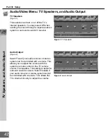
Page 42: ...urround sound A V receiver Audio Output Figure 2 Select Fixed if your audio receiver or stereo system can be controlled with a remote This allows you to adjust the volume with the system s remote control or the TV remote control if compatible This setting is better for surround sound receivers Select Variable if your audio receiver or stereo system cannot be controlled with a remote This allows th...

Page 43: ...d time using Ex tended Data Service XDS time data This data is automatically retrieved from a PBS channel or other channel carrying this serv ice Time Zone Figure 2 When Auto has been selected for the Clock Setting you need to select the correct time zone Atlantic Eastern Central Mountain Pacific Alaska or Hawaii for your area Daylight savings Figure 2 WhenAuto has been selected for the Clock Sett...

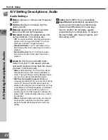
Page 44: ...es are Stereo Default setting The TV will play stereo broadcasts in stereo and mono broadcasts in mono The word Stereo will be displayed when you tune to a channel broadcasting stereo SAP Second Audio Program Additional monaural soundtrack that you cannot hear during normal TV viewing The SAP signal might be related to the program you are watching such as a soundtrack in a foreign language or unre...

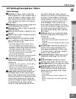
Page 45: ...ontrast provides a slider to adjust the white to black level Low contrast shows a variety of shades in darker images while high contrast shows darker images more uniformly black and makes colors appear more vibrant Brightness provides a slider to adjust the overall brightness of the picture Sharpness provides a slider to adjust the detail and clarity Color provides a slider to adjust the color int...

Page 46: ... yard line watching the game The Mitsubishi total home theater system is the next best thing to being there Ahome theater immerses you in both video and audio to a point of surrealism The core of the home theater system is your bigscreen television the biggest one your room can accommodate ...

Page 47: ...R Control 51 Special Functions 52 Operation of PIP and POP 52 53 Display Formats 54 55 POW ER IN FO PAUSE REC FF F W D REW R EV PLAY STOP 3 6 9 QV VOLUME GUID E EXCH ENTER CANCEL MENU V C HIP FORMAT PIP CH 1 7 SQV 4 IN PUT SLEEP VID EO HOME THEATER AUDIO MUTE 2 5 8 0 CHANNEL ADJU ST PIP INPUT PIP POP HOME TV AUDIO CABLE D BS D TV DVD VCR ...

Page 48: ...XCH Select a channel number or menu item Exchange PIP or POP and main TV picture 15 HOME Exit on screen menus and return to TV viewing 16 ADJUST Navigate menus change set tings and move the PIP on screen loca tion 17 CANCEL Clear SQV some menu entries and numbers inputted by Number buttons 18 MENU Display on screen menu system 19 INFO Display on screen summary of the current input used and any bro...

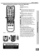
Page 49: ...nto fire Use only AAA batteries Operating the Remote Control You can use the remote to control the TV CABLE DBS DTV VCR DVD andAUDIO products Select the product you want to control by moving the slide switch 1 of figure 1 to the appropriate position The remote control has been preset to operate the TV and other Mitsubishi products To program the remote control to operate other products see Use of ...

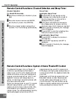
Page 50: ... disappear Channel Selection Sleep Timer and System 4 Home Theater IR Control RemoteControlFunctions System4HomeTheaterIRControl The Mitsubishi System 4 Home Theater IR Control is a special feature that makes it easier to use your TV with a digital surround sound A V receiver Once your equipment is properly connected and set up your TV and digital A V receiver will change inputs to gether to match...

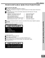
Page 51: ...any Input Rename To DVD Satellite Receiver connected to any Input Rename To DBS Digital Television Receiver on DTV Input Cannot Be Renamed Remote Control programmed to operate your other A V Devices by System 4 properly activated IR emitters properly connected and placed Operation VCR as example To watch your VCR 1 Turn on the TV and A V Receiver 2 Move slide switch to VCR 3 Point remote at the TV...

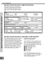
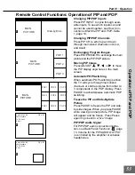
Page 52: ...least 10 sec onds and press PIP POP The next time you activate PIP POP the last used PIP POP format will be displayed first Remote Control Functions Special Functions When your remote control has been Pro grammed to operate another manufacturer s product the function performed on each layer can vary The most common functions are VCR POWER PLAY PAUSE FF FWD CHANNEL up down REC STOP REW REV Mitsubis...

Page 53: ...e through memorized channels or strobe pictures from other A V components in the POP display Press PAUSE to activate pause automatic POP switching Freeze the PIP and Side By Side Picture Press PAUSE to freeze the PIP and side by side images When you press PAUSE while viewing normal picture PIP image will appear and be frozen Press Pause again to go back to a live image PIP POP Audio Signal For PIP...

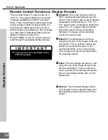
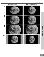
Page 54: ...have 1 78 1 or 1 85 1 aspect ratios Anamorphic DVDs that have the 2 35 1 aspect ratio will still dis play black bars at the top and bottom Narrow 4 3 images will be stretched evenly from side to side The Zoom format is not available during PIP POP functions Display Formats 4 Narrow This format will display narrow 4 3 images in their original shape and add stationary black side bars to fill the scr...

Page 55: ...55 Part IV Operation Standard Picture 4 3 Display Formats Widescreen Picture 16 9 1 2 3 4 ...

Page 56: ...ime when your password is re quested This process temporarily unlocks the TV When entering the V Chip Lock menu this process deletes your old passcode and prompts you to enter a new passcode Appendix A Bypassing the V Chip Lock Lock Bypass Instructions Have Been Filed for Future Reference Appendix A Bypassing the V Chip Lock 57 Cut along the dotted line and file by pass instructions in a safe plac...

Page 57: ......

Page 58: ...patibility Input Levels and Timing with Component Video Y 1 0Vp p includes sync 75ohms Cr 700mVp p 75ohms can also receive signals from outputs labeled R Y and Pr Cb 700mVp p 75ohms can also receive signals from outputs labeled R Y and Pr This input will accomodate most comput ers capable of supporting a VGA SVGA or XGA monitor The only compatible display sync rate is 60Hz This input is compatible...

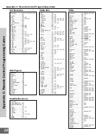
Page 59: ...a 225 226 Denon 234 235 236 Fisher 204 Gerrard 213 Harman Kardon 215 Jensen 223 JVC 232 233 Kenwood 200 208 Magnavox 227 228 Marantz 224 Mclintosh 216 Nakamichi 206 217 Onkyo 209 214 Optimus 203 227 231 230 Panasonic 219 218 221 Philips 223 Pioneer 205 207 Quasar 219 218 221 RCA 203 205 227 231 230 Sansui 203 211 239 Sharp 234 237 Sony 222 Sound sigh 238 TEAC 212 213 210 211 Technics 221 218 219 V...

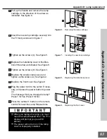
Page 60: ...ailure to do so may cause a fire Appendix D Lamp Replacement Appendix D Lamp Replacement You can confirm the Lamp Elapsed time by selecting the Lamp Status in the Advanced Menu Lamp Life The actual life of the lamp in this television can vary based on the lamp itself the air temperature around the TV while it is operat ing and user s viewing patterns Warmer air or poor ventilation shortens the lam...

Page 61: ...l lamp cover in the direction of the arrow as indicated See figure 4 6 Loosen the two screws of the lamp car tridge See figure 5 If you cannot loosen please use a phillips screwdriver Figure 1 Removing the front cover 2 1 3 Figure 2 Removing the wooden lamp cover 4 Figure 3 Loosen the screws of the wooden lamp cover Figure 4 Removing the metal lamp cover 5 6 Figure 5 Loosen the screws of the lamp ...

Page 62: ...over See figure 9 14 Plug the power cord to the outlet if neces sary and press the power button to power on The message Did you change the lamp Press 1 for Yes Press 0 for No 15 Press the number 1 button on the remote control for reset the Lamp Elapsed time 7 8 10 Figure 6 Removing the lamp cartridge Figure 7 Inserting the new lamp cartridge Figure 8 Replacing the metal lamp cover Figure 9 Replaci...

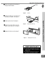
Page 63: ...cover in the direction of the arrow as indicated See figure 1 3 Loosen the wing nuts on the wooden filter cover and remove See figure 2 4 Loosen the screw of the filter tray See figure3 5 Remove the filter tray See figure 4 Filter cleaning Figure 1 Removing the front cover 2 1 3 Figure 2 Removing the wooden filter cover Figure 3 Loosing the screws of the filter tray Figure 4 Removing the filter tr...

Page 64: ... Tighten up the screw See figure 3 9 Replace the wooden filter cover and tighten up the wing nuts See figure 2 10 Replace the front cover See figure 7 Filter Figure 5 Air filter 7 Figure 6 Replacing the filter tray 10 Figure 7 Replacing the front cover If the filter is damaged or becomes extremely dirty contact your dealer for replacement The power will not turn on if the air filter cover is impro...

Page 65: ...screen into the TV Appendix E Cleaning and Service Appendix E Cleaning and Service Service If you are unable to correct a problem with your TV consult your Mitsubishi dealer or a Mitsubishi Authorized Warranty Service Center DO NOT adjust any controls other than those described in this Owner s Guide DO NOT remove the protective back cover of your TV Menus not described and shown in this owner s gu...

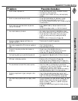
Page 66: ...Use number keys instead of CHANNEL up down Be sure the channel you want to view is in memory Check that the TV is turned to the correct input source for that channel by pressing the INPUT button Make sure the V Chip lock is off page 36 This is part of normal TV operation The TV may be locked The clock may not be set Check to see if the MUTE button is on The TV s Listen to setting may be set to SAP...

Page 67: ...Lock by Time is currently set to disable the V Chip lock the V Chip will not block programing When turning ON the power after unplugging the power cord or opening the lamp cover If you replaced the lamp press number 1 button on the remote control If you did not replace the lamp press number 0 button on the remote control or wait for 30 seconds Appendix F TroubleShooting Appendix F TroubleShooting ...

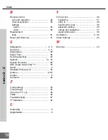
Page 68: ...usting 66 E Español 33 EXCH button on remote 48 53 F Filter cleaning 64 Formats display 54 Front Control Panel 12 H Home Theater IR System connection 22 I Important Safeguards 4 Installing batteries 49 L Lamp replacement 61 Language 33 Level Sound 44 Listen to 44 Locked 38 57 M Maintenance 64 Memorize channels 33 Mitsubishi Limited Warranty 71 N Naming channels 35 Naming inputs 33 P Passcode 36 57...

Page 69: ...Spanish 31 33 Special Functions 52 SQV Super Quick View 35 Stand 4 Standard Picture 4 3 55 Surface 4 66 Surges 5 Surround 44 T Time setting 43 Timer Sleep 50 Timer turn TV on 39 Treble 44 Troubleshooting 67 TV Speakers 42 U Unpacking 9 Upgradeable 9 V V Chip Lock 36 bypassing 57 entry to 36 hours lock by time 38 passcode setting 36 ratings and categories 37 signal information 36 Ventilation 4 66 V...

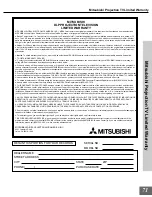
Page 70: ...HI dealer is required when requesting warranty service Present your sales receipt or other document which establishes proof and date of purchase THE RETURN OF THE OWNER REGISTRATION CARD IS NOT A CONDITION OF WARRANTY COVERAGE However please return the Owner Registration Card so that we can contact you should a question of safety arise which could affect you d To obtain a replacement UHP lamp duri...

Page 71: ...00 332 2119 or email us at To order replacement or additional remote controls or owner s guides call 800 553 7278 or visit our website at 2000 Mitsubishi Digital Electronics America Inc 871D303A10 Designed and Printed in U S A MDEAservice bigscreen mea com www mitsubishi tv com ...

Reviews: