


16.2 Cautionary and requested points during installation
– 67 –
No.
Item
Explanation
Precaution for service
Possible failure
Corrective action (Remarks)
1
2
3
4
5
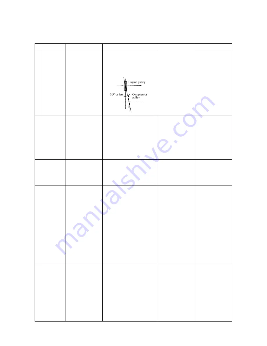
Direct coupled
type unit
Pulley
alignment
Route of
compressor
hoses
Surrounding
temperature of
compressor
hose
Refrigerant
piping
Low pressure
piping
(Excluding the
hose)
•
When installing the
compressor with the
bracket on the vehicle's
engine, adjust the pulley
alignment between
compressor and engine.
•
Since the engine vibrates,
install a hose which
absorbs vibration of the
installed compressor.
•
Influence of engine heat
on the compressor hose
•
Penetration of moisture
•
Penetration of dust
•
Be most sure to keep
moisture and dust from
entering the piping in
order to avoid the
refrigerant cycle from
being damaged by them.
•
Insulate from heat the
piping from the
evaporator outlet to
sucking pipe of the
compressor. (excluding
hose)
•
Branch the pipe of Type
2.
1. Adjust the misalignment to 0.5 degrees
or less. For visual check, tighten the
string.
2. Adjust the tension of the belt with the
tension gauge.
1. Since the compressor may vibrate
approx. 15mm upward/downward and
leftward/rightward, prevent the
surrounding parts from interfering with
each other.
Install the distance rubber near each
part.
2. Bend the hose at the largest possible
curve.
1. Route the hose at the surrounding area
of 80°C or less.
If it is inevitably routed near the exhaust
pipe, install the protector to suppress the
surface temperature to 80°C or less.
1. Work on piping connection under a roof,
avoiding a rainy day.
2. Because copper dust may enter the pipe
from its cut and flared area, perform air
blow (N2 blow) after processing.
3. Don't place piping materials (copper
pipe) on the floor, ground etc, where it is
dusty.
4. When glazing, pass N2 gas into the
piping.
5. Perform evacuation for more than 60
minutes, and reaching of evacuation
should be over –0.1MPa (750mmHg).
6. Don't use the copper pipe which has
been left alone for long and inside of
which is rusted.
1. Pass the low pressure pipe thru the heat
insulated tube.
2. Apply vinyl tape on the connected area
of the tube.
3. Make the route of the piping as short as
possible.
4. Use the branch pipe specified by our
company.
1. Abnormal wear of V belt
2. Trouble of idle pulley
3. Abnormal seal of
compressor shaft
1. The hose is holed.
2. The flared area of the
ferrule is cracked.
3. Poor cooling results from
gas leakage.
1. The hose is holed.
2. The hose is punctured.
3, The ferrule gets off from
the hose.
1. Clogging of water and
dust in the expansion
valve and, clogging of
the dryer.
1. Rising of sucked gas
temperature
Rising of delivered gas
temperature
Early deterioration of
compressor oil
Breaking of compressor
2. Oil is unevenly
distributed.
1. Recondition, adjust or
replace the bracket.
2.
—
3. Replace the compressor.
1. Add the stay for fixture.
2. Add the distance rubber.
1. Change the route of the
hose.
2. Manufacture the heat
protector of aluminum
plate or similar.
1. Investigation of
abnormality on no
freezing reveals that
many of the causes are
due to sticking of copper
dust.
2. Perform evacuation after
applying pressure in
order to check for gas
leakage from glazed area,
etc. To check for leakage
after glazing, leave the
pipe alone for 5 minutes
to maintain –0.1MPa
(750mmHg).
3. Plug the cut of the
refrigerant piping.
1. Apply insulation tube to
the low pressure piping
in order to keep the
sucked gas temperature
from rising.


