background image

6

 Cautions for refrigerant piping work


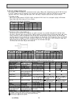
New refrigerant R410A is adopted for replacement inverter series. Although the refrigerant piping work for R410A is same   


as for R22, exclusive tools are necessary so as not to mix with different kind of refrigerant. Furthermore as the working 


pressure of R410A is 1.6 times higher than that of R22, their sizes of flared sections and flare nuts are different.

  1

 Thickness of pipes


 Because the working pressure of R410A is higher compared to R22, be sure to use refrigerant piping with thickness  


 shown below. (Never use pipes of 0.7mm or below.)

  2

 Dimensions of flare cutting and flare nut

The component molecules in HFC refrigerant are smaller compared to conventional refrigerants. In addition to that, 
R410A is a refrigerant, which has higher risk of leakage because its working pressure is higher than that of other refrig-
erants. Therefore, to enhance airtightness and intensity, flare cutting dimension of copper pipe for R410A has been 
specified separately from the dimensions for other refrigerants as shown below. The dimension B of flare nut for R410A  
also has partly been changed to increase intensity as shown below. Set copper pipe correctly referring to copper pipe 
flaring dimensions for R410A below. For 1/2 and 5/8 inch, the dimension B changes. 
Use torque wrench corresponding to each dimension.

  3

 Tools for R410A (The following table shows whether conventional tools can be used or not.)

1/4
3/8
1/2
5/8
3/4

6.35
9.52

12.70
15.88
19.05

0.8
0.8
0.8
1.0

0.8
0.8
0.8
1.0
1.0

Nominal

dimensions(inch)

Diagram below: Piping diameter and thickness

Outside

diameter (mm)

Thickness (mm)

R410A

R22

1/4
3/8
1/2
5/8
3/4

6.35
9.52

12.70
15.88
19.05

9.1

13.2
16.6
19.7

9.0

13.0
16.2
19.4
23.3

Nominal

dimensions(inch)

Flare cutting dimensions

Outside

diameter

Dimension A (     )

+0

-0.4

(mm)

R410A

R22

1/4
3/8
1/2
5/8
3/4

6.35
9.52

12.70
15.88
19.05

17.0
22.0
26.0
29.0

17.0
22.0
24.0
27.0
36.0

Nominal

dimensions(inch)

Flare nut dimensions

Outside

diameter

Dimension B

(mm)

R410A

R22

Gauge manifold
Charge hose
Gas leak detector
Refrigerant recovery equipment
Refrigerant cylinder
Applied oil

Safety charger

Charge valve

Vacuum pump

Flare tool

Bender
Pipe cutter
Welder and nitrogen gas cylinder
Refrigerant charging scale
Vacuum gauge or thermis-
tor vacuum gauge and 
vacuum valve
Charging cylinder

Air purge, refrigerant charge
and operation check
Gas leak check
Refrigerant recovery
Refrigerant charge
Apply to flared section

Prevent compressor malfunction 
when charging refrigerant by 
spraying liquid refrigerant
Prevent gas from blowing out 
when detaching charge hose
Vacuum drying and air
purge

Flaring work of piping

Bend the pipes
Cut the pipes
Weld the pipes
Refrigerant charge
Check the degree of vacuum. (Vacuum 
valve prevents back flow of oil and refri-
gerant to thermistor vacuum gauge)
Refrigerant charge

Tool exclusive for R410A
Tool for HFC refrigerant
Tool exclusive for R410A
Ester oil and alkylbenzene
oil (minimum amount)
Tool exclusive for R410A

Tool exclusive for R410A

Tools for other refrigerants can 
be used if equipped with adop-
ter for reverse flow check
Tools for other refrigerants 
can be used by adjusting 
flaring dimension
Tools for other refrigerants can be used
Tools for other refrigerants 
can be used

Tool exclusive for R410A

Tools and materials

Use

R410A tools

Can R22 tools be used?

(Usable if equipped 

      with adopter for rever-
      se flow)
     (Usable by adjusting 
      flaring dimension)

Can R407C tools be used?

Ester oil:
Alkylbenzene oil: minimum amount

(Usable if equipped 

      with adopter for rever-
      se flow)

(Usable by adjusting 

      flaring dimension)

: Prepare a new tool. (Use the new tool as the tool exclusive for R410A.)
: Tools for other refrigerants can be used under certain conditions.
: Tools for other refrigerants can be used.

Dimension A

Dimension B

OCH533A

Summary of Contents for PUHZ-SW100VHA-BS.UK

Page 1: ...of model PUHZ SW75VHA BS PUHZ SW100VHA BS PUHZ SW100YHA BS PUHZ SW120VHA BS PUHZ SW120YHA BS Note This manual describes only service data of the outdoor units PUHZ SW75VHA BS UK PUHZ SW100VHA BS UK PU...

Page 2: ...20X VM6B EHPT20X YM9B EHST20C VM6HB UK EHST20C YM9HB UK EHST20C VM6B UK EHST20C YM9B UK EHST20C VM6EB UK EHST20C YM9EB UK EHST20C VM6SB UK EHPT20X VM2HB UK EHPT20X VM6HB UK EHPT20X YM9HB UK EHPT20X VM...

Page 3: ...rench Gas leak detector Charge hose Tools for R410A Contamination inside refrigerant piping can cause deterio ration of refrigerant oil etc If dirt dust or moisture enters into refrigerant cycle that...

Page 4: ...7 Refrigerant cylinder Only for R410A Top of cylinder Pink Cylinder with syphon 8 Refrigerant recovery equipment 1 Cautions for service 1 Perform service after recovering the refrigerant left in unit...

Page 5: ...ery device to collect the refrigerant Use new pipes for SW75 SW100 and SW120 models The existing pipe thickness does not meet speci cations or the pipes are damaged 2 4 PRECAUTIONS FOR SALT PROOF TYPE...

Page 6: ...29 0 17 0 22 0 24 0 27 0 36 0 Nominal dimensions inch Flare nut dimensions Outside diameter Dimension B mm R410A R22 Gauge manifold Charge hose Gas leak detector Refrigerant recovery equipment Refrige...

Page 7: ...nt level regardless of the length 10m max and 5m min of piping The additional refrigerant charging work during installation often causes prob lems Heretofore it is completely eliminated This unique sy...

Page 8: ...C 45 C Cooling A35 W7 Outside air temperature Dry bulb 35 C Outside air temperature Wet bulb 24 C Water temperature inlet outlet 12 C 7 C Cooling A35 W18 Outside air temperature Dry bulb 35 C Outside...

Page 9: ...Single 50Hz 230V OUTDOOR UNIT REFRIGERANT PIPING 1 3 19 A kW W kW min CFM dB dB mm in mm in mm in kg lbs kg lbs L mm in mm in Power supply phase cycle voltage Max current External finish Refrigerant c...

Page 10: ...ower supply phase cycle voltage Max current External finish Refrigerant control Compressor Model Motor output Starter type Protection devices Crankcase heater Heat exchanger Fan Fan drive No Fan motor...

Page 11: ...PUHZ SW120VHA BS UK PUHZ SW120YHA UK PUHZ SW120YHA BS UK 4 6 4 8 5 0 5 6 6 2 6 8 7 5 4 6 U V U W W V Service Ref Compressor model Winding Resistance ANB33FNEMT at 20 C 0 19 0 19 0 19 PUHZ SW100VHA UK...

Page 12: ...500 1000 2000 4000 8000 APPROXIMATE THRESHOLD OF HEARING FOR CONTINUOUS NOISE OCTAVE BAND SOUND PRESSURE LEVEL dB 0 dB 0 0002 bar NC 60 NC 50 NC 40 NC 30 NC 20 NC 70 PUHZ SW100VHA UK PUHZ SW100VHA BS...

Page 13: ...kout Front trunking hole Knockout Power supply wiring hole 2 27Knockout 9 2 40 45 65 92 27 55 23 73 63 Rear piping hole Knockout Rear trunking hole Knockout Power supply wiring hole 2 27Knockout 9 2 E...

Page 14: ...27Knockout W 92 92 65 45 40 27 55 23 73 63 Front piping hole Knockout Front trunking hole Knockout Power supply wiring hole 2 W27Knockout W 9 2 145 145 220 30 145 81 219 71 71 Bottom piping hole Knock...

Page 15: ...F1 F2 F3 F4 X51 X52 X54 Switch Function Switch Model Select Switch Model Select Switch Function Switch Switch Function Switch Switch Function Switch Switch Pump Down Connector Emergency Operation Con...

Page 16: ...n Connector Emergency Operation Connector Connection for Option Connector Connection for Option Connector Connection for Option Connector Connection for Option Connector Connection for Option LED Oper...

Page 17: ...witch Pump Down Connector Emergency Operation Connector Connection for Option Connector Connection for Option Connector Connection for Option Connector Connection for Option Connector Connection for O...

Page 18: ...e NOT always against the ground S3 terminal has DC 24 V against S2 terminal However between S3 and S1 these terminals are NOT electrically insulated by the transformer or other device S1 S2 S3 S1 S2 S...

Page 19: ...flow in heating Pressure sensor 63HS Low pressure switch 63L PUHZ SW100VHA PUHZ SW100VHA BS PUHZ SW100YHA PUHZ SW100YHA BS PUHZ SW75VHA UK PUHZ SW75VHA BS UK PUHZ SW120VHA PUHZ SW120VHA BS PUHZ SW120...

Page 20: ...tch to ON again 3 Because the unit automatically stops in about 2 to 3 minutes when the refrigerant collecting operation is completed LED1 off LED2 lit be sure to quickly close the gas stop valve If L...

Page 21: ...heck the symptom and check the installation environment refrigerant amount weather when the trouble occurred matters related to wiring and etc 2 Reset error code logs and restart the unit after nishin...

Page 22: ...ard V the noise filter Y Refer to 10 7 4 Check connection of reactor DCL or ACL SW75VHA Check connection of LO and NO on the outdoor noise filter circuit board Check connection of R and S on the outdo...

Page 23: ...oor unit connecting wire Total wiring length 80m including wiring connecting each indoor unit and between indoor and outdoor unit Also check if the connection order of flat cable is S1 S2 S3 3 Check t...

Page 24: ...minutes after and during defrosting 1 Disconnection or contact failure of connector TH4 TH34 on the outdoor controller circuit board 2 Defective thermistor 3 Defective outdoor controller circuit board...

Page 25: ...rd U6 Power module Check abnormality by driving power module in case overcurrent is detected UF or UP error condition 1 Outdoor stop valve is closed 2 Decrease of power supply voltage 3 Looseness disc...

Page 26: ...wiring SW VHA 4 Replace outdoor power circuit board SW VHA 5 Replace outdoor power circuit board SW100 120V YHA 6 Replace outdoor noise filter circuit board SW75VHA 7 Replace outdoor converter circui...

Page 27: ...1 Disconnection of compressor wiring 2 Defective circuit of current sensor on outdoor power circuit board 3 Decrease of power supply voltage 1 Correct the wiring U V W phase to compressor Refer to 10...

Page 28: ...ng abnormality If the unit is not normal after replacing indoor controller board in group control indoor controller board of address 0 may be abnormal 1 Contact failure at transmission wire of remote...

Page 29: ...the other to sub 2 Remote controller is connected with only one indoor unit 3 The address changes to a separate setting 4 6 Diagnose remote controller a When RC OK is displayed remote controllers hav...

Page 30: ...detects Tcond C or more and compressor operation frequency is less than or equal to 25 Hz Detection is inoperative during defrosting 1 Overcharge of refrigerant 2 Defective refrigerant circuit clogs...

Page 31: ...perature adjuster turns on the compressor will not stop operating even if tem perature adjuster is turned off Compressor stops operating immediately when turning off by the remote controller 12Normal...

Page 32: ...nnot be set Are timer settings invalid If the timer can be set WEEKLY SIMPLE or AUTO OFF appears in the remote controller display PLEASE WAIT appears in the remote controller display The initial setti...

Page 33: ...after turning on the main power Normal The start up diagnosis will be over in around 2 minutes Miswiring of indoor outdoor connecting wire Breaking of indoor outdoor connecting wire S3 Defective indoo...

Page 34: ...oard are blown Check the wiring of the outdoor unit Check if the wiring is bad Check if the fuses are blown The fuses on the outdoor controller circuit board will be blown when the indoor outdoor conn...

Page 35: ...oor controller circuit board Replace the outdoor controller circuit board Normal Only the unit which has the refrigerant address 0 supplies power to the remote controller Set the refrigerant address t...

Page 36: ...act of the remote controller wire Check the voltage of the terminal block TB5 connecting the remote controller wire If it is not between DC 10V and DC16V the indoor controller board must be defective...

Page 37: ...r FILTER from the display See the operation manual that came with the product for how to clean the filters STANDBY is displayed on the screen This is displayed when the unit starts HEAT operation when...

Page 38: ...r unit is controlling the airflow amount in order to keep the optimum operating condition A sound similar to water flowing is heard from the unit This is not a malfunction This is the sound which is h...

Page 39: ...airflow direction doesn t change Up down vane left right louver 1 Check if the vane is set to a fixed position Check if the vane motor connector is removed 2 Check if the air conditioner has a functio...

Page 40: ...100YHA BS UK PUHZ SW120YHA BS UK 1 2 3 4 5 M Gray Orange Red Yellow Black Parts name Check points Disconnect the connector then measure the resistance with a tester At the ambient temperature 10 30 Th...

Reviews: