Mitsubishi MELFA 4D-2CG5100-PKG-E Instruction Manual Download Page 21

2

 System configuration


Component Devices

  2-10 


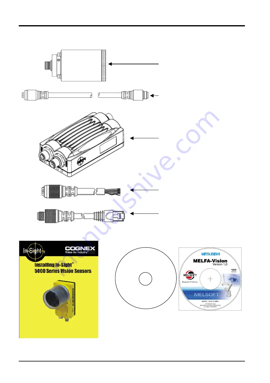
The composition of 4D-2CG-5400R-PKG(Remote Head) are shown in figures. 


   Installation guide 

Figure 2-2 Basic set(Remote Head Type) composition 


Remote Head Camera 

 
Camera Cable 

 
Network Vision sensor 

 
Breakout Cable 

 
Network Cable 

In‑Sight Software CD‑ROM 

MELFA-Vision CD-ROM 

Summary of Contents for MELFA 4D-2CG5100-PKG-E

Page 1: ...Mitsubishi Industrial Robot Series Network Vision Sensor Instruction Manual 4D 2CG5100 PKG E 4D 2CG5400 PKG E 4D 2CG5401 PKG E 4D 2CG5403 PKG E 4D 2CG5400C PKG E 4D 2CG5400R PKG E BFP A8520...

Page 2: ......

Page 3: ......

Page 4: ...Revision History Printing Date Instruction Manual No Revision Contents 2006 10 02 BFP A8520 First Edition...

Page 5: ...ancies or unclear points are found please contact your dealer The information contained in this document has been written to be accurate as much as possible Please interpret that items not described i...

Page 6: ...on the start switch etc This also applies to maintenance work with the power source turned ON Indication of teaching work in progress Provide a fence or enclosure during operation to prevent contact...

Page 7: ...this could lead to malfunctioning by noise or to electric shock accidents Indicate the operation state during robot operation Failure to indicate the state could lead to operators approaching the rob...

Page 8: ...he controller Provide an earth leakage breaker that packed together on the primary power supply of the controller as protection against electric leakage Confirm the setting connector of the input powe...

Page 9: ......

Page 10: ...14 3 SPECIFICATIONS 3 16 3 1 Network vision sensor specifications 3 16 3 1 1 External Dimensions of Network Vision Sensor 5100 5400 5401 5403 5400C 3 17 3 1 2 External Dimensions of Network Vision Se...

Page 11: ...7 5 1 Check the MELFA Vision Camera Image 7 74 7 5 2 Comparison of the position data for the work recognized by the vision sensor and the position data received by the robot 7 74 8 MAINTENANCE 8 76 8...

Page 12: ...ensors and robots 9 134 9 4 1 Systems with one robot controller and multiple vision sensors 9 134 9 4 2 Systems with one vision sensor and multiple robot controllers 9 135 10 TROUBLESHOOTING 10 137 10...

Page 13: ...1 2 1 Summary 1 1 What A Network Vision Sensor Is The network vision sensor is an option that makes it possible to discriminate the position of various types of work and transport process assemble in...

Page 14: ...MELFA Vision Network Vision Support Software has image log functions so it is possible to check the image state when an error occurred 3 Easy setting Connect a vision sensor by just connecting the Et...

Page 15: ...sensor 1 Loading Unloading Machined Parts Figure 1 1 Example of Loading Unloading Machined Parts 2 Processed Food Pallet Transfer Figure 1 2 Example of Processed Food Pallet Transfer 3 Lining Up and...

Page 16: ...all Electrical Product Assembly Figure 1 4 Example of Small Electrical Product Assembly 5 Lining Up Parts Figure 1 5 Example of Lining Up Parts 6 Small Electronic Parts Mounting Figure 1 6 Example of...

Page 17: ...m Threshold This is the cutoff point for degree of matching scores Shutter speed This is the exposure time the time during which the CCD accumulates charge Sort This rearranges the order in which data...

Page 18: ...5m 1 Camera cable 5m 4 Remote head camera installation bracket 4 In Sight 5000 series Installation guide CD ROM Part 206 6364 2 In Sight Explorer In Sight Display Control In Sight OPC Server Software...

Page 19: ...5 15 Network cable 30m CCB 84901 1006 30 2m CCB 84901 0101 02 5m CCB 84901 0102 05 10m CCB 84901 0103 10 Breakout cable 15m CCB 84901 0104 15 5m CCB 84901 0303 05 10m CCB 84901 0304 10 Camera cable 15...

Page 20: ...ion of the basic set All in one design are shown in figures Installation guide Figure 2 1 Basic set All in one design composition In Sight Software CD ROM MELFA Vision CD ROM Lens cover O ring Thread...

Page 21: ...ition of 4D 2CG 5400R PKG Remote Head are shown in figures Installation guide Figure 2 2 Basic set Remote Head Type composition Remote Head Camera Camera Cable Network Vision sensor Breakout Cable Net...

Page 22: ...imum of 350 mA CPU Intel Pentium III 700MHz or equivalent or faster Memory size 256 MB min Hard disk Available capacity of 200 MB min OS Microsoft Windows 2000 Service Pack 4 Microsoft Windows XP Prof...

Page 23: ...ation When One Camera Is Used Part name Format Manufacturer Q ty Remarks Robot controller CRn 500 series 1 Software K6 or later Robot main unit All models 1 Expansion option box CR1 EB3 1 For CR1 cont...

Page 24: ...HR533 1 Vision sensor In Sight 5000 series 2 Software 3 20 or later Breakout cable 2 Network vision sensor basic set 4 Network cable Mitsubishi Electric 2 Lens 4 C mount lens 1 2 24V power supply 3 1...

Page 25: ...ware K6 or later Robot main unit All models 3 Expansion option box CR1 EB3 3 For CR1 controller Ethernet interface card 2A HR533 3 Vision sensor Network vision sensor basic set 4 1 Software 3 20 or la...

Page 26: ...nfiguration 2 15 System configuration example 4 Up to three robot controllers can be connected at the same time to one vision sensor so prepare the necessary quantity for the number of robot controlle...

Page 27: ...nterface 6 Ethernet Communication lines 3 lines Lighting Integrated lighting option Controller pad VGA Application development In Sight Explorer PC Lens mounting C or CS C C CS Voltage condition 24VDC...

Page 28: ...l Dimensions of Network Vision Sensor 5100 5400 5401 5403 5400C Externals dimensions of Network Vision Sensor 5100 5400 5401 5403 5400C is shown below please refer when you fix the Vision sensor Figur...

Page 29: ...3 18 3 1 2 External Dimensions of Network Vision Sensor 5400R Externals dimensions of Network Vision Sensor 5400R is shown below please refer when you fix the Vision sensor Unit mm Figure 3 2 External...

Page 30: ...ations 3 19 Network vision sensor specifications Unit mm Figure 3 3 External Charts of Network Vision Sensor 5400R Remote Head part Unit mm Figure 3 4 External Charts of Network Vision Sensor 5400R Bl...

Page 31: ...l vision sensor commands 1 Versions K5 and earlier can communicate with a vision sensor by combining the previous Open Print Input Close commands Versions K7 and later can communicate with a vision se...

Page 32: ...and the recognized quantity and recognized work position are checked 6 Robot controller communication settings It is easy to make settings for communicating between the robot controller and vision se...

Page 33: ...the software p 5 23 E n d Equipment preparation and connection Chapter 5 Step1 Work recognition test p 6 33 Vision Sensor Initial Settings Chapter 6 Step2 Vision sensor default settings p 6 29 Calibra...

Page 34: ...List of Configuration When One Camera Is Used Part name Format Manufacturer Q ty Remarks Robot controller CRn 500 series 1 Software K6 or later Robot main unit All models 1 Teaching box R28TB 1 Ether...

Page 35: ...ent Installation For details on any controller other than a CR1 see the CRn Controller Instruction Manual From Controller Setup and Basic Operations to Maintenance 3 Optional Equipment Installation n...

Page 36: ...rnet straight cable to the hub and the other end to the robot controller s Ethernet interface card Figure 5 1 Ethernet Cable Connection Hub In Sight5100 5400 PC Tool Robot Robot controller 24V power s...

Page 37: ...s CD ROM drive When the installation program starts automatically the following screen is displayed Figure 5 3 In Sight Software Setup Screen 3 Select the language displayed on the right side of the...

Page 38: ...uter s CD ROM drive The Setup screen will be started up automatically 2 If the screen does not start up automatically carry out the following procedure a Select the start button and run b Check the CD...

Page 39: ...installation of MELFA Vision Instruction Manual pdf Misc This folder contains the user registration application form for faxing 4 Installation check When the installation is complete the installed sof...

Page 40: ...s necessary to make this initial setting with the In Sight Connection Manager installed with 5 3 1 Vision sensor dedicated software In Sight Explorer installation The method for this initial setting i...

Page 41: ...ddress for each vision sensor connected Also if you restart by switching Off then On the power for all the vision sensors set the MAC addresses are automatically displayed in a list 4 Click the Next b...

Page 42: ...administrator for the IP address to set Here is an example in which an IP address of 10 50 0 100 is set 7 Click the Configure button cut off the power for the vision sensor wait at least 5 seconds the...

Page 43: ...st 1 From the Windows Start menu click All Programs MELSOFT Application RT ToolBox MELFA Vision to start MELFA Vision 2 Select the appropriate vision sensor from the displayed vision sensor list then...

Page 44: ...n functions see 9 2 MELFA Vision Function Details 2 Title 3 Menu 4 Tool buttons 5 Vision Sensor Information 1 Window 6 Job Editing 8 Camera image 7 Calibration data creation 9 Status bar Figure 6 2 Ma...

Page 45: ...ounted on the vision sensor Manual trigger Requests the vision sensor to capture an image Online Select whether the vision sensor can be controlled from the outside online or editing of image processi...

Page 46: ...This displays the information for logged on vision sensors Figure 6 4 Vision Sensor Information Pattern Matching Table 6 3 Vision Sensor Information Items Pattern Matching Control Operation Name This...

Page 47: ...era image Black when logged off 9 Status bar This displays the vision sensor mode image information for the mouse position and PC image log reception status Figure 6 8 Status Bar Table 6 5 Status Bar...

Page 48: ...ck from the tool bar to put MELFA Vision into live image mode Put the work to be recognized under the vision sensor and check the resulting image with MELFA Vision Camera Image Figure 6 9 Image Check...

Page 49: ...djust the lens Diaphragm Figure 6 12 Camera Lens adjustment If the appropriate brightness can not be achieved by just adjusting the Diaphragm provide different lighting Too bright Figure 6 13 Example...

Page 50: ...6 Vision Sensor Settings 6 39 Work recognition test 4 If the focus is not appropriate adjust the lens focus Figure 6 15 Example in Which The Image Is Out of Focus...

Page 51: ...ly one robot results output as robot absolute coordinate values as an example For details on other image processing see 9 3 1 Templates provided for MELFA Vision 1 In the Job List on the left side of...

Page 52: ...ng range Explanation Exposure 0 032 1000 This adjusts the exposure time for images captured Lowering this value shortens the image take in time and reduces the amount of light accumulated on the CDD a...

Page 53: ...External The image is taken in at the rising edge of a discrete I O 1 input bit or serial command Manual The image is taken in when the F5 key is pressed Network The image is taken in when the trigge...

Page 54: ...gistered work is detected from the area enclosed by the red frame The area in which the work is detected can be changed with the mouse or keyboard If you use the keyboard each time the F9 key is press...

Page 55: ...mage on the main screen The registered work is enclosed by the red frame For operations use the mouse or keyboard If you use the keyboard each time the F9 key is pressed the area adjustment mark chang...

Page 56: ...nd a red circle is displayed at Camera Image on the main screen Move this circle with the mouse or keyboard to specify what position to send to the robot for the registered work If you use the keyboar...

Page 57: ...nd angle with the angle for the registered work as 0 Sort By None X Y Returns the recognized work results in the specified sort order When None is specified the results are returned with the work sort...

Page 58: ...he image are recognized and they are displayed with pointer mark and a number from 0 in order of highest degree of match attached to each piece of work When 3 is set When you click the Job Editing scr...

Page 59: ...aximum detection count of 10 Threshold of 40 When you click the Job Editing screen Test button even though there is one piece of work at the top left two pieces of work are recognized Large work is al...

Page 60: ...nd angle 45 is set When you click the Job Editing screen Test button only work is detected that is within the 45 range with the registered work angle as 0 When Start angle 45 end angle 180 is set When...

Page 61: ...splayed with a number from 0 in order of the X direction from top to bottom in the figure above of the frame specified with the search area specification Sort direction Y When you click the Job Editin...

Page 62: ...ell Position tab 7 When you want to check not only the image but also the numeric data in the image processing results click Sensor Display Test Result s in the main screen menu In the initial display...

Page 63: ...t up till now to the vision sensor When you click the Save button a Confirmation screen is displayed to check that you want to save the settings If you click No the save is cancelled If you click Yes...

Page 64: ...On the robot controller power 2 Set the robot controller IP address With the teaching box R28TB turn the key switch in the Enable direction MENU 5 Maintenance 1 Parameters Input NETIP INP Input the I...

Page 65: ...Communication Server screen If the communication parameters have not been set yet all the information is written in red Click the Setting button to display the Communication Setting screen Click Meth...

Page 66: ...light blue If a frame is green redo the setting 5 This sets the parameters for the robot controller and vision sensor to communicate From MELFA Vision menu select Controller Communication Setting to...

Page 67: ...e button On the displayed Device Setting screen switch On the Change the Parameter to connect Vision checkbox then input the vision sensor IP address as the IP Address Click the OK button and check th...

Page 68: ...be switched Off then On again to put the parameter change into effect Click the Yes button and wait for the robot controller power supply to be reset When the robot controller starts click the Read bu...

Page 69: ...nt used in calibration work Prepare four marking labels copy the marking sheet in the appendix align it with the image field of vision and make enlarged and reduced copies and the calibration jigs for...

Page 70: ...ode or from the MELFA Vision tool bar click to exit live image mode 5 From the MELFA Vision main screen select No 1 in the Calibration Data List This section explains No 1 data creation 6 On the Creat...

Page 71: ...ettings Calibration Setting 7 60 7 Specify the first point on the vision sensor Click the Image button for the first point Use the mouse or the arrow keys to move the mark to mark 1 then press the Ent...

Page 72: ...ttings 7 61 Calibration Setting 8 Specify the second point on the vision sensor Click the Image button for the second point Use the mouse or the arrow keys to move the mark to mark 2 then press the En...

Page 73: ...ettings Calibration Setting 7 62 9 Specify the third point on the vision sensor Click the Image button for the third point Use the mouse or the arrow keys to move the mark to mark 3 then press the Ent...

Page 74: ...tings 7 63 Calibration Setting 10 Specify the fourth point on the vision sensor Click the Image button for the fourth point Use the mouse or the arrow keys to move the mark to mark 4 then press the En...

Page 75: ...point to acquire the robot s current position 12 Specify the second point with the robot Use the teaching box to move the robot hand to the second point On the Create Calibration Data screen click th...

Page 76: ...obot s current position 15 Input a comment In the Create Calibration Data screen Comment column input a comment to make the meaning of this work easy to understand then click the Create Data button 16...

Page 77: ...with the robot coordinate system From the MELFA Vision main screen Job Vision Program List select Job1 job then click the Edit button On the displayed Job Editing screen click the Processing Conditio...

Page 78: ...ing Place the work under the vision sensor then click the Job Editing screen Test button From the MELFA Vision menu when you click Sensor Recognition Test Results the coordinates for the recognized wo...

Page 79: ...n Setting 7 68 19 The Job Editing screen Calibration specification has been changed so the recognition conditions are saved Click the Job Editing screen Save button 20 Close the Job Editing screen Cli...

Page 80: ...10 000 7 0 4 P2 300 000 400 00 100 000 180 000 0 000 90 000 7 0 10 IF M_NVOPEN 1 1 THEN When logon has not been completed for vision sensor number 1 20 NVOPEN COM2 AS 1 Connects with the vision sensor...

Page 81: ...position name P0 for the evacuation point in the position edit screen POS column or scroll the position names with FORWD or BACKWD to display P0 Press STEP MOVE ADD ADD ADD twice to store the current...

Page 82: ...putting the vision sensor online From the MELFA Vision Main screen menu click Sensor Online or click on the toolbar button 7 4 2 Test by executing each step Open the robot program created with the tea...

Page 83: ...to display the override at the Status Number Press the UP DOWN button to set the Status Number display to o 010 This sets the robot override to 10 Press the CHNG DISP button to display the robot progr...

Page 84: ...ings 7 73 Executing the automatic operation test The main screen Camera Image displays the recognition results and the robot transports all the work recognized by the vision sensor After transporting...

Page 85: ...s correct 1 Check the main screen Camera Image and check that the is on the recognized work 2 Check if the position of the is the position specified with the Job Editing screen Output position setting...

Page 86: ...controller and the vision sensor in the explanation up till now COM2 then click the Recognition Details button 4 Compare the Display Test Result s screen and Detail Monitor screen P_NVS1 values to ch...

Page 87: ...though this function can be used with the specified vision sensor either logged on or logged off since the robot and vision sensor access can be slowed down by file transfer operations normally back u...

Page 88: ...or is selected that is not logged on but that vision sensor can be logged on with the currently logged on user name and password 4 A confirmation screen is displayed so check the contents then click t...

Page 89: ...k using MELFA Vision 1 Display the MELFA Vision restore screen From the MELFA Vision menu click Sensor Restore to display the Restore screen 2 Specify the folder to transfer from The folder to transfe...

Page 90: ...ting files To restore the vision sensor setting file proc set and the host table file hosts net vision sensor network setting file too click the Yes button Only restore a network setting file to the s...

Page 91: ...estoration 8 80 7 When the restoration is complete the completion message is displayed To reflect the restoration settings restart the vision sensor When the OK button is clicked display returns to th...

Page 92: ...plains cloning work using MELFA Vision 1 Display the MELFA Vision cloning screen From the MELFA Vision menu click Sensor Clone To to display the Clone screen 2 Select the vision sensor to be the cloni...

Page 93: ...n the cloning work starts the indicator progresses as on the screen below To cancel cloning work that is underway click the Stop button 6 When the cloning is complete the completion message is display...

Page 94: ...the same user name and password may be set for both Also enter here the same user name and password as for the Job Editing screen Image Log tab User Name of FTP and Passward of FTP For details on the...

Page 95: ...ision startup screen From the MELFA Vision menu click Sensor Startup to display the Startup screen 2 Select whether to start up online or offline and what job to load when starting the vision sensor T...

Page 96: ...loaded edited and stored Normally log on with this right when using MELFA Vision Protected This user is not permitted to do FTP writing under the initial conditions However it is possible for writing...

Page 97: ...so set the required items and click the OK button 4 To delete an existing a user select the user from the User List screen list and click the Delete button Check the contents of the confirmation scree...

Page 98: ...Sample sentence Shows a sample sentence Explanation Shows the functions in detail and caution item Error Shows an error generated when the command word is executed 9 1 2 MELFA BASIC IV Commands Here a...

Page 99: ...n sensor number of this command are shared so use numbers other than those specified with the Open command COM number and File number Example Normal example Error example 10 OPEN COM1 AS 1 10 OPEN COM...

Page 100: ...e is closed with a main program End command The line is also closed by a program reset 11 If an interrupt condition is established while this command is being executed the interrupt processing is exec...

Page 101: ...ies the cell range rows and columns in which the results recognized by the vision sensor are stored The contents of the specified cell are stored in any of the status variables P_NVS 30 M_NVS 30 10 C_...

Page 102: ...meric type data M_NVS is converted into the numerical value for a numeric variable and it preserves it When the character which cannot be converted is included it preserves it as 0 M_NVS is two dimens...

Page 103: ...tasking it is necessary to execute the NVOPEN command in the task using this command Also use the vision sensor number specified with the NVOPEN command 5 When type from 4 to 7 is specified for Type t...

Page 104: ...obot at the same time Use this command on any one of the robots Example of tracking system with three robots and one vision sensor Controller Controller Controller master Image capture request Data re...

Page 105: ...sion program name exceeds 15 characters an abnormal vision program name error occurs 6 If a vision program name uses a character other than 0 9 A Z or _ including lowercase letters an abnormal vision...

Page 106: ...unctions 9 95 Vision Sensor Dedicated Commands and Status Variables 18 If the communications line is cut while this command is being executed an abnormal communications error occurs and the robot cont...

Page 107: ...tops immediately 4 If the specified vision program name is already loaded the command ends with no processing 5 When this command is used with multi tasking it is necessary to execute the NVOPEN comma...

Page 108: ...d stores this in P_NVS1 170 300 NVCLOSE 1 Cuts the line with the vision sensor connected to COM2 Explanation 1 Outputs the image capture request to the specified vision sensor and acquires the encoder...

Page 109: ...ror occurs 4 If the NVOPEN command is not opened with the number specified as the vision sensor number an abnormal vision sensor number specification error occurs 5 If the vision program s image captu...

Page 110: ...sor connected to COM2 Explanation 1 Starts the specified vision program in the specified vision sensor 2 This command moves to the next step after it has verified that the vision sensor has received t...

Page 111: ...rogram name exceeds 15 characters an abnormal vision program name error occurs 6 If a vision program name uses a character other than 0 9 A Z or _ including lowercase letters an abnormal vision progra...

Page 112: ...rt cell End cell Can not be omitted Specifies the cell range in which the results recognized by the vision sensor are stored The contents of the specified cell are stored in any of the status variable...

Page 113: ...If the data type for an argument is incorrect a syntax error in input command statement error is generated 2 If there is an abnormal number of command arguments too many or too few an incorrect argume...

Page 114: ...is already cut execution shifts to the next step 4 Because up to seven vision sensors can be connected at the same time Vision sensor numbers are used in order to identify which vision sensor to close...

Page 115: ...logged onto Sample sentence 100 IF M_NVOPEN 1 1 THEN If vision sensor number 1 is not connected 110 NVOPEN COM2 AS 1 Connects with the vision sensor connected to COM2 and sets its number as number 1...

Page 116: ...IF M_NVOPEN 1 1 THEN When logon has not been completed for vision sensor number 1 110 NVOPEN COM2 AS 1 Connects with the vision sensor connected to COM2 120 ENDIF 130 WAIT M_NVOPEN 1 1 Connects with v...

Page 117: ...ximum number of pieces of work that a vision sensor can recognize at one time is 255 but the maximum number of sets of work information that a robot can acquire is 30 Sample sentence 100 IF M_NVOPEN 1...

Page 118: ...ta is cleared to 0 for all axes for a power supply reset 4 Also if anything other than 0 is specified as the type with the NVPST command or NVIN command all axes are cleared to 0 5 If the acquired dat...

Page 119: ...1 THEN If vision sensor number 1 log on is not complete 110 NVOPEN COM2 AS 1 Connects with the vision sensor connected to COM2 and sets its number as number 1 120 ENDIF 130 WAIT M_NVOPEN 1 1 Connects...

Page 120: ...type with the NVPST command or NVIN command the data is cleared to 0 3 If the acquired data is a vision program function or character string 0 is stored in the corresponding axis 4 When using multi m...

Page 121: ...ariable for storing scores 100 IF M_NVOPEN 1 1 THEN When logon has not been completed for vision sensor number 1 110 NVOPEN COM2 AS 1 Connects with the vision sensor connected to COM2 and sets its num...

Page 122: ...et END command or power supply reset Also if anything other than 2 and 3 and 6 and 7 is specified as the type with the NVPST command or NVIN command the data is cleared to null 4 If the acquired data...

Page 123: ...ion Details This section explains MELFA Vision functions other than those explained in Chapter 5 0 9 2 1 MELFA Vision Main Screen For explanations concerning the MELFA Vision main screen see 6 2 1 Sta...

Page 124: ...unt of recognized pieces of work is 0 File Name Images captured with the vision sensor are stored as bit map bmp files on the PC This specifies the file name Up to 50 files names can be specified Max...

Page 125: ...or the work recognized by the vision sensor are stored from the displayed start cell position to the displayed end cell position Robot 2 1 The coordinates robot 2 coordinates for the work recognized b...

Page 126: ...ensor name Use DHCP Server Check this when using the DHCP server to allocate the IP address IP Address Input the IP address Subnet Mask Defines which part of the IP address shows the network and which...

Page 127: ...ern matching 2 Relative coordinates 30 21 1 22 4 23 10 24 20 25 Blob binarization processing 3 30 26 1 27 4 28 10 29 20 30 Color 7 Absolute coordinates 1 30 1 Pattern matching blobs edges histograms I...

Page 128: ...positions for each robot by capturing one image 6 It is necessary for the vision program to prepare beforehand an area in which to store the work position data that the robot acquires Expanding this a...

Page 129: ...settings using pattern matching image processing only one robot results output as robot absolute coordinate values as an example 1 In the Job Vision Program List on the left side of the main MELFA Vis...

Page 130: ...nge Explanation Blob Black white Either Select the color of the work tobe recognized black or white or any desired color Color Setting Background Black white This specifies the color black or white th...

Page 131: ...lts in the specified sort order When None is specified the results are returned with the work sorted in order of high recognition ratio This sorting is used for cases such as when multiple work pieces...

Page 132: ...ettings using pattern matching image processing only one robot results output as robot absolute coordinate values as an example 1 In the Job Vision Program List on the left side of the main MELFA Visi...

Page 133: ...White Balance button is not clicked cannot accurately recognize the color like Figure 9 1 When you do not click White Balance button Figure 9 2 When you do not click White Balance button White Balance...

Page 134: ...ich wants to be recognized with the frame and click the Enter key Representation ON OFF Whether the specified color is acquired in RGB Red Green Blue information or it acquires it in HIS Hue Intensity...

Page 135: ...c is detected Enclose the color which wants to be recognized with Acawac The area in which the work is detected can be changed with the mouse or keyboard If you use the keyboard each time the F9 key i...

Page 136: ...program detailed explanation 4 2 Changes to the gray scale imagery by the color which specifies Camera Image Select Filter CheckBox is ON and Test button is clicked Specified color is displayed in whi...

Page 137: ...ed explanation 9 126 4 3 Color is adjusted Value of Threshold is changed and Test button is clicked For instance when green is recognized more emphatically the value of Green is increased and other it...

Page 138: ...rogram detailed explanation 4 4 When work is recognized specifying not only Hue but also Saturation and Intensity Representation is changed Representation CheckBox is ON all the values of the item of...

Page 139: ...led explanation 9 128 4 5 Color is adjusted Value of Threshold is changed and Test button is clicked For instance when recognize the vivid color work the value of Saturation is increased and other ite...

Page 140: ...he recognized work is registered Refer to 6 2 3 Image processing settings for registration method 6 The condition of recognizing it is specified Pattern Search Area tab is displayed and the recognized...

Page 141: ...tes provided for MELFA Vision are pattern matching and blobs When using a robot using other image processing write the vision program using In Sight Explorer installed on the PC with 5 3 1 Vision sens...

Page 142: ...g the acquired values However in the example above since a total of 12 data transfers are required for cells J81 through L84 the transfer time becomes longer After change The value converts errors int...

Page 143: ...text string the previous time 190 MFLG1 0 Clears the flag showing that all the information has been acquired 200 WHILE MFLG1 0 Loops until all the information is acquired 210 CGET C_NVS1 MROW 1 Acqui...

Page 144: ...m above the work placement position P2 570 MOV P2 Moves to the work placement position P2 580 DLY 0 1 Wait time of 0 1 second 590 HOPEN 1 Opens hand 1 600 DLY 0 2 Wait time of 0 2 second 610 MVS P2 10...

Page 145: ...hapter explains the construction of these systems 9 4 1 Systems with one robot controller and multiple vision sensors This section only explains those aspects of the setting method for constructing a...

Page 146: ...1 L85 0 10 Starts the vision program and acquires the results 80 NVPST 2 Job1 E76 J81 L85 0 10 Starts the vision program and acquires the results 90 NVPST 3 Job1 E76 J81 L85 0 10 Starts the vision pro...

Page 147: ...50 WAIT M_IN 10 1 Checks that Robot 2 has received the notice 60 M_OUT 10 0 Switches Off the reception possible signal to Robot 2 Operates the robot with the results received 200 NVCLOSE Robot 2 10 I...

Page 148: ...vision sensor number and re execute Or check the communications parameters L 3141 The NVOPEN command is not executed No NVOPEN command was executed before execution of a command communicating with th...

Page 149: ...an 15 characters L 8622 Vision program not present The specified program does not exist in the specified vision sensor Check whether the specified vision program exists in the specified vision sensor...

Page 150: ...mage capture specification of camera external or manual L 8650 Put online The vision sensor is offline Put the vision sensor online to enable control from the outside L 8660 Not permitted to control v...

Page 151: ...registration Table 11 2 Comparison of Functions for Recognition Pattern Registration Function Network vision sensor Built in vision sensor Area size change Yes Yes Specification of coordinates for out...

Page 152: ...rence in the communication time when connecting directly with a cross cable without using a hub 2 About the affect of other equipment connected to the network When equipment other than the network vis...

Page 153: ...ix Calibration No marking sheet 11 142 11 2 Calibration No marking sheet This is a marking sheet used in calibration work Enlarge or reduce it as necessary to match the size of the field of vision of...

Page 154: ...BFP A8520 Printed in Japan on recycled paper Specifications are subject to change without notice HEAD OFFICE MITSUBISHI DENKI BLDG MARUNOUCHI TOKYO 100 8310 NAGOYA WORKS 1 14 YADA MINAMI 5 HIGASHI KU...

Reviews: