6
FEATURES AND FUNCTIONS
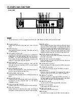
REAR VIEW
N
•
Ensure the power cord is not plugged into the mains outlet before connecting to any rear terminals.
1
AC power socket
This socket connects to the power cord. Insert the cord
firmly.
2
SET IN terminal
Input terminal for alarm recording. The alarm sensor is
connected here.
3
RST (RESET) IN terminal
Input terminal to stop alarm recording when “ALARM REC
DURATION” of the “RECORDING SET UP” menu is set
to “MAN1”. The alarm reset switch is connected here.
This terminal can also be used to set the on-screen clock
when set to any mode other than “MAN1”.
4
REC IN terminal
Input terminal to start/stop recording. Also, use this
terminal for series recording (P.17) or synchronous
recording (P.18).
5
GND (GROUND) terminal
When a lead connected to other terminals requires a
ground, connect the ground lead here.
6
ALM (ALARM) OUT terminal
Output terminal to indicate alarm recording to an external
alarm.
7
MODE OUT terminal
Output terminal to indicate the VCR’s mode of operation.
Selected by setting “MODE OUT” on the “REAR
TERMINAL” menu.
8
CLK (CLOCK) OUT terminal
Output terminal to control an external camera switcher.
9
CALL OUT terminal
Output terminal to indicate when tape has finished
recording or if there has been a problem during recording.
A
RESET button
When pressed, the present time, alarm recording list, power
loss list and the number of tape use will be erased. While
the button is pressed, the power is cut off from the VCR. If
there is a cassette tape in the VCR and the button is
released, the power indicator will light and the tape will fast
forward for a few seconds. The VCR will then switch off.
B
RS-232C IN terminal (D-SUB 9pin)
Input terminal to connect with a personal computer via
RS-232C cross cable.
C
RS-232C OUT terminal (D-SUB 9pin)
Output terminal to connect the VCR with other VCRs via
RS-232C cross cable.
D
S-VIDEO OUT connector
Output connector for video signal. (S-VIDEO connector)
E
S-VIDEO IN connector
Input connector for video signal. (S-VIDEO connector)
F
REMOTE jack
Remote control is possible by connecting the optional
remote control unit (R-7100) here. Refer to page 40.
G
VIDEO OUT connector
Output connector for video signal (BNC connector). If
the power switch is turned OFF, the signal from the VIDEO
IN connector is looped out to this connector.
H
VIDEO IN connector
Input connector for video signal (BNC connector).
I
AUDIO OUT connector
Audio output connector (RCA pin).
J
AUDIO IN connector
Audio input connector (RCA pin).
K
MIC IN jack
Input jack for a microphone with 600 ohms impedance.
VIDEO
OUT
IN
IN
OUT
ÉMIC
AUDIO
RESET
REMOTE
SET
RST
IN
REC
GND ALM MODE
CLK CALL
OUT
IN
OUT
S-VIDEO
OUT
IN
RS-232C
1
5
2
3
4 6
7 8
9 A
B
ED
C
F
G
H
K J I
Summary of Contents for HS-S8300E(BRS)
Page 42: ...872C193C3 PRINTED IN JAPAN...


