


- 21 -
CHARGE SPRING
CHARGE ASSY
SWING LEVER
REEL DISK (SP side)
Both Sides
(Front/Back)
MAIN PLATE ASSY
a
b
c
Back
Front
Fig. 2-29
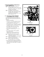
2-29.CHARGE SPRING, SWING LEVER,
CHARGE ASSY
SET POSITION :
Normal
Remove the following parts before replacing the
CHARGE SPRING, SWING LEVER, CHARGE ASSY.
Refer to the corresponding items to install them.
• STAY PLATE (Item 2-2)
• BOTTOM ASSY (Item 2-3)
• MOTOR HOLDER (Item 2-16)
• PINCH ARM CAP (Item 2-17)
• PINCH UNIT (Item 2-17)
• BRAKE CAM PLATE (Item 2-19)
(Removal)
1. Remove the CHARGE SPRING shown in the Fig. 2-
29 from the SWING LEVER.
2. Remove the SWING LEVER shown in the Fig. 2-29.
3. Release the Part
a
of the CHARGE ASSY shown in
the Fig. 2-29 from the Part
b
of the MAIN PLATE
ASSY to remove the CHARGE ASSY.
(Installation)
1. Apply GREASE (MULTEMP AC-DM)[859D055O90] to
the parts on the MAIN PLATE ASSY specified in the
Fig. 2-29.
2. Install the CHARGE ASSY.
3. Install the SWING LEVER inserting the Part
c
of the
SWING LEVER in the Fig. 2-29 into the groove in the
MAIN PLATE ASSY.
4. Install the CHARGE SPRING to the SWING LEVER.
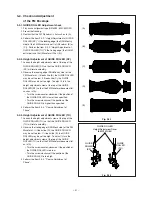
2-30.LOADING ARM ASSY (SP), LOADING
ARM ASSY (TU)
SET POSITION :
Upside down
(Removal)
1. Release the catch (
a
) of the LOADING ARM ASSY
(SP) shown in the Fig. 2-30-1 to remove the
LOADING ARM ASSY (SP).
Note :
Be sure to replace the removed LOADING ARM
ASSY (SP) with a new one.
2. Remove the screw (
b
) fastening the SPACER PLATE
shown in the Fig. 2-30-1 to remove the SPACER
PLATE.
3. Remove the LOADING ARM ASSY (TU) shown in the
Fig. 2-30-1.
a
b
SPACER PLATE
LOADING
ARM ASSY (TU)
LOADING ARM
ASSY (SP)
MAIN PLATE ASSY
GREASE (MULTEMP AC-DM)
Fig. 2-30-1
Summary of Contents for HS-HD1100U
Page 57: ... 1 PARTS LIST 1 CABINET ASSEMBLY r 1 3 4 3 i o 0 2 6 t 7 2 1 ...
Page 61: ...DECK ASSEMBLY ...
Page 77: ......


