


List of Parameters
Explanation of Parameters
"Pr." is the abbreviation of parameter.
Torque boost
䊏
Basic functions <default state>
䊏
Extended functions
Parameter
0
1
2
3
4
5
6
7
8
9
30
79
Torque boost
Maximum frequency
Minimum frequency
Base frequency
Multi-speed setting (high speed)
Multi-speed setting (medium speed)
Multi-speed setting (low speed)
Acceleration time
Deceleration time
Electronic thermal O/L relay
Extended function display selection
Operation mode selection
0~15%
0~120Hz
0~120Hz
0~120Hz
0~120Hz
0~120Hz
0~120Hz
0~999 s
0~999 s
0~50A
0, 1
0~4, 7, 8
0.1%
0.1Hz
0.1Hz
0.1Hz
0.1Hz
0.1Hz
0.1Hz
0.1 s
0.1 s
0.1A
1
1
6%/5%/4% (Note 4)
60Hz
0Hz
60Hz
60Hz
30Hz
10Hz
5 s
5 s
Rated output current (Note 3)
0
0
Name
Setting range
Minimum setting unit
Default setting
Function
Basic functions
Standard operation functions
Current
detection
Restart
Terminal function
selection
Operation selection functions
Multi-speed operation functions
Remote
setting
Display functions
PID control
Slip
compensation
Automatic
torque boost
Communication/PU function (Note 2)
Calibration functions
Auxiliary
functions
Output terminal
functions
2nd functions
Current
detection
1. The shaded parameters can be changed even during operation.
2. This parameter is provided only with the type having the RS-485 communication function.
3. This will be 85% of the rated output current for 0.75K or less.
4. This will be 5% for FR-S540-1.5K and 2.2K, and 4% for FR-S540-3.7K.
(Notes)
By setting parameter 30 to 1, the following extended function parameters can be set.
Parameter
Function
Name
10
11
12
13
14
15
16
17
19
20
21
22
23
24
25
26
27
28
29
31
32
33
34
35
36
37
38
39
40
41
42
43
44
45
46
47
48
49
DC injection brake operation frequency
DC injection brake operation time
DC injection brake voltage
Starting frequency
Load pattern selection
JOG frequency
JOG acceleration/deceleration time
RUN key rotation direction selection
Base frequency voltage
Acceleration/deceleration reference frequency
Stall prevention function selection
Stall prevention operation level
Stall prevention operation level
compensation factor at double speed
Multi-speed setting (speed 4)
Multi-speed setting (speed 5)
Multi-speed setting (speed 6)
Multi-speed setting (speed 7)
Stall prevention operation reduction starting frequency
Acceleration/deceleration pattern
Frequency jump 1A
Frequency jump 1B
Frequency jump 2A
Frequency jump 2B
Frequency jump 3A
Frequency jump 3B
Speed display
Frequency setting voltage gain frequency
Frequency setting current gain frequency
Start-time ground fault detection selection
Up-to-frequency sensitivity
Output frequency detection
Output frequency detection at reverse rotation
2nd acceleration/deceleration time
2nd deceleration time
2nd torque boost
2nd V/F (base frequency)
Output current detection level
Output current detection signal delay time
Parameter
Function
Name
50
51
52
53
54
55
56
57
58
59
60
61
62
63
64
65
66
67
68
69
70
71
72
73
74
75
76
77
78
80
81
82
83
84
85
86
87
Zero current detection level
Zero current detection time
Control panel display data selection
Frequency setting operation selection
FM terminal function selection
Frequency monitor reference
Current monitor reference
Restart coasting time
Restart cushion time
Remote setting function selection /
Frequency setting storage function selection
RL terminal function selection
RM terminal function selection
RH terminal function selection
STR terminal function selection
RUN terminal function selection
A, B, C terminal function selection
Retry selection
Number of retries at alarm occurrence
Retry waiting time
Retry count display erase
Soft-PWM setting
Applicable motor
PWM frequency selection
0 to 5V/0 to 10V selection
Input filter time constant
Reset selection/ PU stop selection
Cooling fan operation selection
Parameter write disable selection
Reverse rotation prevention selection
Multi-speed setting (speed 8)
Multi-speed setting (speed 9)
Multi-speed setting (speed 10)
Multi-speed setting (speed 11)
Multi-speed setting (speed 12)
Multi-speed setting (speed 13)
Multi-speed setting (speed 14)
Multi-speed setting (speed 15)
Parameter
Function
Name
88
89
90
91
92
93
94
95
96
97
98
99
n 1
n 2
n 3
n 4
n 5
n 6
n 7
n 8
n 9
n 10
n 11
n 12
n 13
n 14
n 15
n 16
n 17
c 1
c 2
c 3
c 4
c 5
c 6
c 7
c 8
CLr
ECL
PID operation selection
PID proportional band
PID integral time
PID upper limit
PID lower limit
PID control set point during PU operation
PID differential time
Motor rated slip
Slip compensation time constant
Constant output area slip compensation selection
Automatic torque boost selection
(motor capacity)
Motor primary resistance
Communication station number
Communication speed
Stop bit length
Parity check presence/absence
Number of communication retries
Communication check time interval
Wait time setting
Operation command write
Speed command write
Link start mode selection
CR/LF selection
E
2
PROM write validity selection
PU display language
PU buzzer sound control
PU contrast adjustment
PU main display screen data selection
PU dislocation detection/PU setting lock
FM terminal calibration
Frequency setting voltage bias frequency
Frequency setting voltage bias
Frequency setting voltage gain
Frequency setting current bias frequency
Frequency setting current bias
Frequency setting current gain
Parameter for manufacturer setting. Do not set.
Parameter clear
Alarm history clear
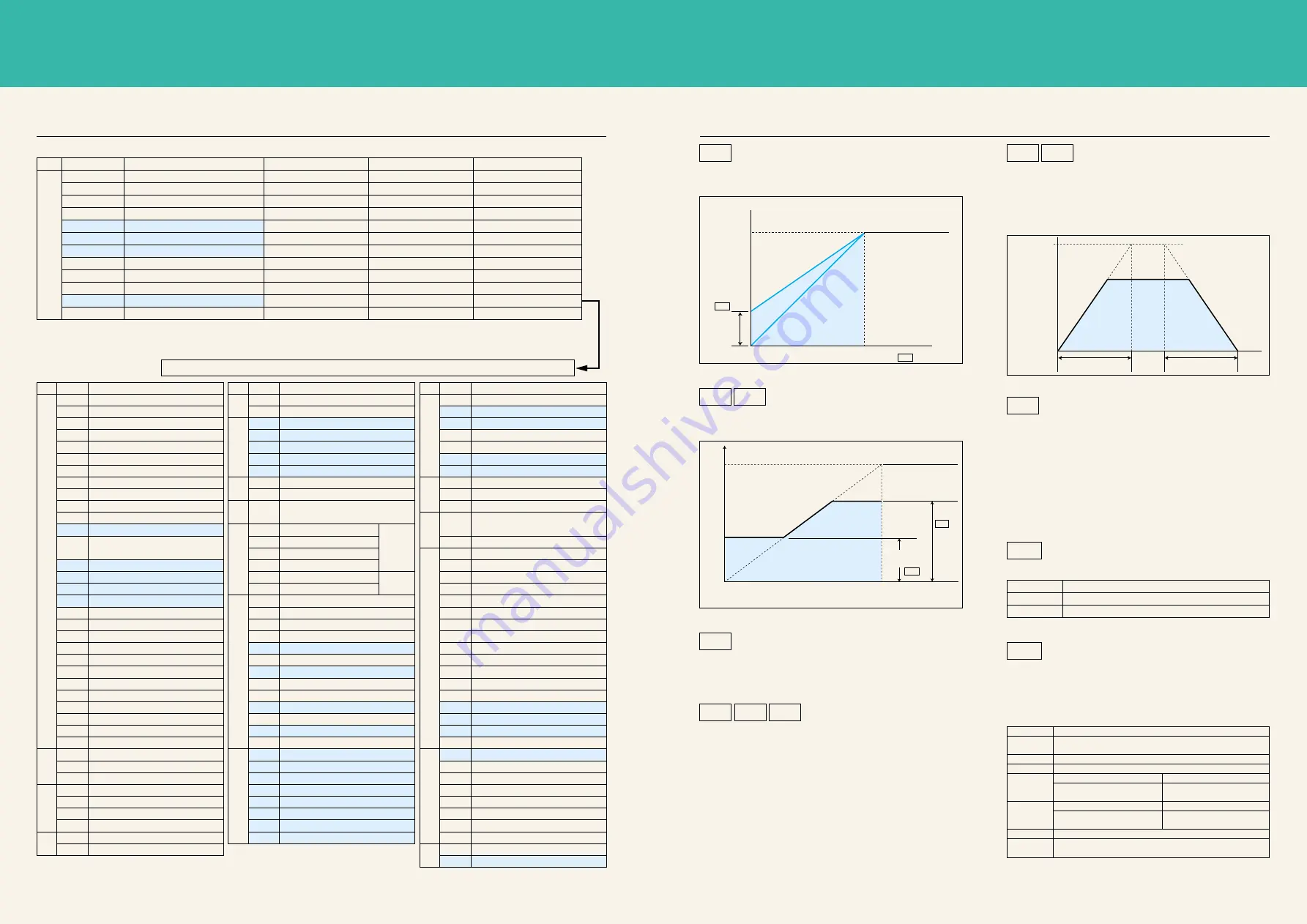
Pr.20
Pr.7
Pr.8
Acceleration time Deceleration time
100%
Frequency setting signal
5V
(10V)
(20mA)
Maximum
frequency
Minimum
frequency
Pr.1
Pr.2
100%
Setting
range
Output frequency
Output voltage
Output frequency
Output frequency
Base frequency
Pr.0
Pr.3
Pr.0
●
The motor torque in the low frequency area
can be adjusted according to the load.
Pr.7
Acceleration/deceleration time
Pr.8
●
For the acceleration time, set the time to reach
the acceleration/deceleration reference frequency
Pr. 20 (default value: 60Hz) from 0Hz,
and for the deceleration time, set the time to reach
0Hz from Pr. 20 (default value: 60Hz).
Electronic thermal O/L relay
Pr.9
●
The setting value to protect the motor from
overheating can be set as a current value.
Normally, the motor rated current is set for 50Hz.
●
When 0A is set, the motor protective function
will not activate. (The inverter output transistor's
protective function will activate.)
●
When connecting multiple motors, set an external
thermal relay for each motor.
Extended function display selection
Pr.30
●
Set this to display and set the extended function parameters.
Operation mode selection
Pr.79
●
The inverter operation modes include operation
with external signal and operation with the PU
(setting dial, touch keys). The mode can be fixed
to one mode, or two modes can be used together.
Pr.1
Maximum/minimum frequency
Pr.2
Base frequency
Pr.3
●
The upper limit and lower limit of the output
frequency is clamped.
●
Set the base frequency (reference frequency for motor
rated torque) between 0 and 120Hz according to the motor.
Pr.4 Pr.5
Multi-speed setting
Pr.6
●
Various speeds (RH, RM, RL) can be selected
just by changing the contact signal from an
external source.
●
Each speed (frequency) can be set
between 0 and 120Hz while the inverter is running.
Setting value
0
1
Setting value
0
1
2
3
4
7
8
Details
Display only basic functions
Display all parameters
Details
Operation is possible by changing between PU
(setting dial, touch key) operation or external operation.
Operation frequency
Setting with setting dial
· Multi-speed selection
· 4 to 20mADC input
External terminal (STF/STR)
External terminal signal
(Multi-speed, 0 to 5VDC, etc.)
RUN key
PU operation interlock
Operation mode external signal changeover
Select operation mode by turning PU operation/external operation
mode changeover (X16) signal ON and OFF.
Starting signal
Operation frequency
Starting signal
Operation is possible only with PU (setting dial, touch key) operation.
Only external operation is possible.
*
Refer to the Instruction Manual for details.
Can be selected with
the RL, RM, RH, RT,
AU, STOP, MRS, OH,
REX, JOG, RES, X14,
X16 and STR signals.
(The STR signal can
be assigned only
with Pr. 63.)
Can be selected with the
RUN, SU, OL, FU, RY,
Y12, Y13, FDN, FUP, RL,
LF and ABC signals.
6
7


