


3
Wiring
ENGLISH
3
Wiring
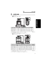
(1) Remove the jumper across terminals P and P1 of the inverter and
connect the reactor.
Minimize the connection cable between the reactor and inverter so that the
length is within 5m. (For the size of the cable, refer to page 4)
The jumper connected across terminals P1 and P must be removed.
Otherwise, the reactor will not exhibit its performance.
When wiring, remove the terminal block cover. After wiring, reinstall the
terminal block cover. (The 200V class 18.5K or higher and the 400V class
75K or higher do not have terminal block covers.)
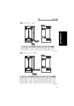
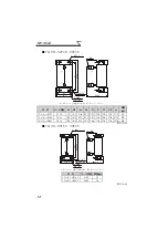
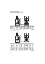
(2) Make selection according to the applied motor capacity. (When the
inverter capacity is larger than the motor capacity, make selection
according to the motor capacity.)
For a motor of less than 0.4kW, choose the option designed for 0.4kW.
(3)
The 55K or lower is usually earthed (grounded) by being mounted
securely to the enclosure. If it is not earthed (grounded) enough through
the enclosure, use an earthing (grounding) cable.
When you are using an earthing (grounding) cable, wire the cable to the
installation hole where varnish is removed.
(Refer to
page 4
for the cable and solderless terminal sizes, and
page 7
for the position of the installation hole where varnish is removed.)
For the 75K or higher, securely earth (ground) the reactor using the earth
(ground) terminal.
CAUTION
1. After wiring, make sure that the terminal block cover has been
reinstalled securely.
2. Do not perform wiring while power is on and the inverter is running.
3. Any person who is involved in the wiring of this equipment
should be fully competent to do the work.
4. Since high-voltage is applied to the inverter terminals P1, P and N,
fully make sure that the input power is off and the voltage across
terminals P and N is not exceeding 50VDC before performing wiring.
5. The terminal block cover is not provided for the 200V class
18.5K or higher.
Provide isolation treatment to avoid contact of terminals.
3-phase AC
power supply
MCCB
R/L1
S/L2
T/L3
Motor
U
V
W
P1
P1
P
MC
M
P/+
N/-
FR-HEL
Inverter
When using a model equipped with
a jumper across terminals P1 and P,
remove the jumper.
The connection cable
should be 5m maximum.


