


Chapter 2 Specifications
2–12
•
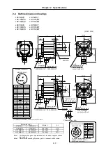
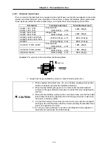
HC902S
(Unit : mm)
45
°
φ
21
5
15
0
□
204
60
φ
250
0
-0.
01
6
0
-0
.0
4
0
φ
42
φ
18
0
81
.5
21.5
MS3102A22-14P
CE05-2A32-17P
278
Oil seal
S45629B
80
85
3
20
25
364
44
Note 2
Note 2
Powe r su p ply
co nn e c to r
Detector
connector
4-
φ
15
Installation hole
Use a hexagon
socket head bolt.
Note 2
Note 2
Note 1. Use a friction coupling (Spun ring, etc.) to connect with the load.
Note 2. Screw hole (M8) for suspension bolt.
Note 3. Refer to section 2-9 for details on the detector connector.
•
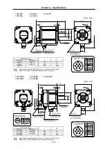
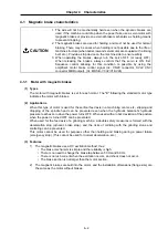
HC902BS
(Unit : mm)
81
.5
Detector connector
MS3102A22-14P
φ
42
φ
18
0
45
°
φ
21
5
φ
250
15
0
□
204
60
4-
φ
15
Installation hole
73.5
Brake connector
MS3102A10SL-4P
Power supply
connector
CE05-2A32-17P
278
80
85
3
20
25
412
44
0
-0
.0
4
0
0
-0
.0
1
6
Use a hexagon socket
head bolt
Oil seal
S45629B
Note 2
Note 2
21.5
Note2
Note2
Note 1. Use a friction coupling (Spun ring, etc.) to connect with the load.
Note 2. Screw hole (M8) for suspension bolt.
Note 3. Refer to section 2-9 for details on the detector connector.
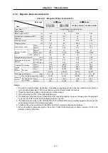
Brake connector
MS3102A10SL-4P
Signal
B1
B2
B
A
Pin
A
B
24VDC with no polarity.
CE05-2A32-17P
D
Signal
U
V
W
B
A
Pin
C
A
B
C
D
Power supply connector
Grounding
CE05-2A32-17P
D
Signal
U
V
W
B
A
Pin
C
A
B
C
D
Power supply connector
Grounding


