background image

4G9 ENGINE (E-W) -

General Information

11A-0-4

4G93

Descriptions

4G93-SOHC

4G93-DOHC

4G93-DOHC-GDI

Type

In-line OHV, SOHC

In-line OHV, DOHC

In-line OHV, DOHC

Number of cylinders

4

4

4

Combustion chamber

Pentroof type

Pentroof type

Pentroof type

Total displacement dm

3

1,834

1,834

1,834

Cylinder bore mm

81.0

81.0

81.0

Piston stroke mm

89.0

89.0

89.0

Compression ratio

10.0, 9.5

10.5

11.7*

1

, 12.0*

2

Valve timing

Intake

valve

Opens

(BTDC)

14

_

20

_

15

_

Closes

(ABDC)

50

_

60

_

56

_

Exhaust

valve

Opens

(BBDC)

58

_

61

_

55

_

Closes

(ATDC)

10

_

15

_

15

_

Lubrication system

Pressure feed, full-

flow filtration

Pressure feed, full-

flow filtration

Pressure feed, full-

flow filtration

Oil pump type

Trochoid type

Trochoid type

Trochoid type

Cooling system

Water-cooled forced

circulation

Water-cooled forced

circulation

Water-cooled forced

circulation

Water pump type

Centrifugal

impeller

type

Centrifugal

impeller

type

Centrifugal

impeller

type

*

1

: Up to 1999 model

*

2

: From 2000 model

PWEE9502-G

E

May 2000

Mitsubishi Motors Corporation

Revised

Summary of Contents for 4G9 series

Page 1: ...AKE AND EXHAUST MANIFOLD 11A 6 1 6a INTAKE MANIFOLD GDI 11A 6a 1 6b EXHAUST MANIFOLD GDI 11A 6b 1 6c INJECTOR AND FUEL PUMP ASSEMBLY GDI 11A 6c 1 6d INTAKE AND EXHAUST MANIFOLD 4G94 GDI for PAJERO io 11A 6d 1 7 WATER PUMP AND WATER HOSE 11A 7 1 8 ROCKER ARMS AND CAMSHAFTS 11A 8 1 8a ROCKER COVER AND CAMSHAFTS MIVEC 11A 8a 1 8b ROCKER ARMS AND ROCKER SHAFT CAPS MIVEC 11A 8b 1 9 CYLINDER HEAD AND VA...

Page 2: ...11A 0 2 PWEE9502 E May 1995 Mitsubishi Motors Corporation NOTES ...

Page 3: ...Valve timing Intake valve Opens BTDC 20_ 14_ 17_ Low speed cam 47 5_ High speed cam Closes ABDC 42_ 58_ 31_ Low speed cam 72 5_ High speed cam Exhaust valve Opens BBDC 54_ 52_ 41_ Low speed cam 70_ High speed cam Closes ATDC 2_ 16_ 11_ Low speed cam 35_ High speed cam Lubrication system Pressure feed full flow filtration Pressure feed full flow filtration Oil pump type Trochoid type Trochoid type ...

Page 4: ... Intake valve Opens BTDC 14_ 20_ 15_ Closes ABDC 50_ 60_ 56_ Exhaust valve Opens BBDC 58_ 61_ 55_ Closes ATDC 10_ 15_ 15_ Lubrication system Pressure feed full flow filtration Pressure feed full flow filtration Pressure feed full flow filtration Oil pump type Trochoid type Trochoid type Trochoid type Cooling system Water cooled forced circulation Water cooled forced circulation Water cooled forced...

Page 5: ... 81 5 Piston stroke mm 95 8 95 8 Compression ratio 9 5 10 6 Valve timing Intake valve Opens BTDC 2_ 15_ Closes ABDC 58_ 51_ Exhaust valve Opens BBDC 58_ 55_ Closes ATDC 10_ 15_ Lubrication system Pressure feed full flow filtration Pressure feed full flow filtration Oil pump type Trochoid type Trochoid type Cooling system Water cooled forced circulation Water cooled forced circulation Water pump ty...

Page 6: ... 11 36 61 G S C Exhaust 37 15 36 65 4G94 SOHC Intake 37 91 37 41 S C Exhaust 37 70 37 20 4G93 DOHC Intake 35 31 34 81 G C Exhaust 35 20 34 70 4G93 DOHC GDI Intake 35 49 34 99 4G93 DOHC GDI Exhaust 34 73 34 23 4G94 DOHC GDI Intake 35 49 34 99 4G94 DOHC GDI Exhaust 34 91 34 41 Valve clearance mm Intake 0 09 Exhaust 0 20 Camshaft journal O D mm SOHC 26 0 DOHC 45 0 Rocker cover and camshaft MIVEC Cams...

Page 7: ...DOHC Intake 104 19 103 69 Exhaust 103 87 103 37 DOHC MIVEC Intake 115 63 115 13 Exhaust 115 63 115 13 DOHC GDI Intake 104 19 103 69 Exhaust 103 87 103 37 Valve spring free length mm SOHC with lash ad juster 50 9 49 9 SOHC with adjust ing screw 49 5 48 5 DOHC 45 0 44 0 DOHC MIVEC 51 5 50 5 DOHC GDI 44 8 43 8 Valve spring out of squareness Max 2_ 4_ Valve stem to valve guide clearance mm Except DOHC...

Page 8: ...10 0 18 0 35 Piston and connecting rod Piston ring to piston ring groove clearance mm No 1 0 03 0 07 0 1 mm No 2 0 02 0 06 0 1 Piston ring end gap mm No 1 4G92 4G93 0 25 0 40 0 8 mm 4G94 0 15 0 30 0 8 No 2 0 40 0 55 0 8 Oil ring SOHC 4G92 4G93 0 20 0 60 1 0 SOHC 4G94 DOHC 0 10 0 35 1 0 Crankshaft pin oil clearance mm 0 02 0 05 0 1 Piston pin press in load N Room temperature 4 500 14 700 Connecting...

Page 9: ...le both intake and exhaust mm 0 05 O S 11 05 11 07 exhaust mm 0 25 O S 11 25 11 27 0 50 O S 11 50 11 52 Oversize rework dimensions of intake valve seat hole mm SOHC 0 30 O S 31 80 31 83 seat hole mm 0 60 O S 32 10 32 13 DOHC 0 30 O S 34 30 34 32 0 60 O S 34 60 34 62 Oversize rework dimensions of exhaust valve seat hole mm SOHC 0 30 O S 29 30 29 32 seat hole mm 0 60 O S 29 60 29 62 DOHC 0 30 O S 30...

Page 10: ...vot bolt 44 Center cover 3 Ignition failure sensor M6 5 Ignition failure sensor M8 23 Ignition failure sensor bracket 10 Cam position sensor 9 Cam position sensor support 13 Cam position sensing cylinder 21 Engine cover 2 9 Timing belt Camshaft sprocket bolt 88 Cam position sensor 9 8 Crank angle sensor 9 8 Timing belt rear cover 11 Timing belt rear upper cover 11 Timing belt tensioner 24 Engine s...

Page 11: ...valve Bolt and washer assembly 9 Vacuum hose and pipe assembly Engine without solenoid valve 10 Solenoid valve assembly 9 Throttle body and EGR system GDI Air intake resonator 9 Intake manifold stay M8 20 Intake manifold stay M10 30 Water hose clamp 13 Water pipe 11 Throttle body 18 Throttle body stay CARISMA from 2001 model SPACE STAR from 2001 model GALANT 24 Throttle body stay For PAJERO io 4G9...

Page 12: ... sensor 44 Intake manifold GDI Vacuum pipe and hose Except for PAJERO io 11 Vacuum pipe and hose For PAJERO io 9 Solenoid valve 9 Fuel pump protector 23 Connector bracket 11 Branch tube M6 x 14 11 Branch tube M6 x 18 9 Intake manifold stay 30 Accelerator cable bracket 9 Vacuum pipe 11 Intake manifold 19 Exhaust manifold GDI Oil level gauge guide 13 Exhaust manifold cover 13 Engine hanger bolt 24 E...

Page 13: ...essure sensor For PAJERO io 18 Spacer 18 Pump camshaft case 23 Injector holder 22 Delivery pipe and injector 11 Intake and exhaust manifold 4G94 GDI for PAJERO io Vacuum pipe and hose 9 Solenoid valve 9 Fuel pump protector 23 Connector bracket 11 Intake manifold stay nut 29 Intake manifold stay bolt 31 Low pressure fuel pipe 9 Intake manifold 20 Exhaust manifold cover 13 Engine hanger 18 Exhaust m...

Page 14: ...3 5 Bearing cap bolt M6 11 Bearing cap bolt M8 24 Beam camshaft cap M6 11 Beam camshaft cap M8 21 Rocker cover and camshafts MIVEC Rocker cover 4 Oil pump 11 Arm spring holder 11 Camshaft bearing cap M6 11 Camshaft bearing cap M8 23 Oil control valve 9 Rocker arms and rocker shaft caps MIVEC Rocker shaft cap 11 Cylinder head and valves CylInder head bolt 74 Nm and then completely loosen finally ti...

Page 15: ... connecting rod Connecting rod cap nut 20 90_ to 100_ Crankshaft cylinder block flywheel and drive plate Bearing cap bolt 25 90_ to 100_ Oil seal case 11 Bell housing cover Flange bolt 10 Bell housing cover Bolt and washer assembly 9 Rear plate SPACE STAR 10 Rear plate Except SPACE STAR 11 Drive plate bolt 98 Flywheel bolt 98 Baffle plate 9 Knock sensor 23 PWEE9502 K E Jun 2002 Mitsubishi Motors C...

Page 16: ...ant temperature sensor 3M Nut Locking Part No 4171 or equivalent As required Engine coolant temperature gauge unit 3M ATD Part No 8660 or equivalent As required Camshaft bearing cap 3M ATD Part No 8660 or equivalent As required Semi circular packing 3M ATD Part No 8660 or equivalent As required Rocker cover 3M ATD Part No 8660 or equivalent As required Beam camshaft cap Mitsubishi Genuine Part No ...

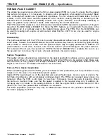
Page 17: ...raper may be lightly hammered in between the joined surfaces In this case however care must be taken to prevent damage to the joined surfaces For removal of the oil pan the special tool Oil Pan Remover MD998727 is available Be sure to use the special tool to remove the oil pan Except aluminium die cast oil pans Surface Preparation Thoroughly remove all substances deposited on the gasket applicatio...

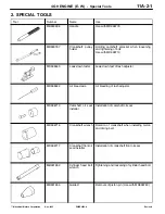
Page 18: ...40 Leak down tester Leak down test of lash adjuster MD998442 Air bleed wire Air bleeding of lash adjuster MD998713 Camshaft oil seal installer Installation of camshaft oil seal MD998716 Crankshaft wrench Rotation of crankshaft when installing piston and timing belt MD998717 Crankshaft front oil seal installer Installation of crankshaft front oil seal MB991653 Cylinder head bolt wrench Tightening a...

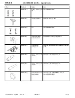
Page 19: ...54 Pin Use with MB990767 MD998767 Tensioner pulley socket wrench Adjustment of timing belt tension MD998772 Valve spring compressor Removal and installation of valve and related parts MD998774 Valve stem seal installer Installation of valve stem seal MD998775 Valve stem seal installer Installation of valve stem seal MD998776 Crankshaft rear oil seal installer Installation of crankshaft rear oil se...

Page 20: ...compressor Compression of valve spring MD998781 Flywheel stopper Holding flywheel and drive plate MB991477 Valve adjusting wrench Adjustment of valve clearance MIVEC MB991478 Valve adjusting wrench feeler gauge set Adjustment of valve clearance MIVEC MB991479 Rocker arm piston checker Adjustment of valve clearance MIVEC MD998784 Valve spring compressor adapter Compression of valve spring MIVEC Use...

Page 21: ... Nm 44 Nm 49 Nm Removal steps 1 Drive belt 2 Alternator 3 Alternator brace AA BA 4 Crankshaft bolt BA 5 Crankshaft pulley BA 6 Front flange 7 Spark plug cable 8 Spark plug 9 O ring 10 Distributor 11 Power steering pump pulley 12 Power steering pump bracket stay 13 Power steering pump bracket NOTE For details of adjustment refer to the relevant model s chassis workshop manual PWEE9502 J E Apr 2002 ...

Page 22: ...lternator brace AA BA 4 Crankshaft bolt BA 5 Crankshaft pulley BA 6 Front flange 7 Spark plug cable 8 Ignition coil 9 Spark plug 10 Ignition failure sensor From 2001 model vehicles for Europe 11 Cam position sensor AA 12 Cam position sensor support 13 Cam position sensing cylinder 14 Power steering pump pulley 15 Power steering pump bracket stay 16 Power steering pump bracket NOTE For details of a...

Page 23: ... brace AA BA 4 Crankshaft bolt BA 5 Crankshaft pulley BA 6 Front flange 7 Spark plug cable 8 Ignition coil 9 Spark plug 10 Ignition failure sensor For Europe 11 Ignition failure sensor bracket For Europe 12 Cam position sensor AA 13 Cam position sensor support 14 Cam position sensing cylinder 15 Power steering pump pulley 16 Power steering pump bracket stay 17 Power steering pump bracket NOTE For ...

Page 24: ...4G9 ENGINE E W Alternator and Ignition System 11A 3 2b Intentionally blank PWEE9502 E E Dec 1998 Mitsubishi Motors Corporation Added ...

Page 25: ...Nm Removal steps 1 Drive belt 2 Alternator 3 Alternator brace AA BA 4 Crankshaft bolt BA 5 Crankshaft pulley BA 6 Front flange 7 Center cover 8 Ignition coil 9 Spark plug cable 10 Spark plug 11 Ignition failure sensor 12 Power steering pump pulley 13 Power steering pump bracket stay 14 Power steering pump bracket NOTE For details of adjustment refer to the relevant model s chassis workshop manual ...

Page 26: ...1 Drive belt 2 Alternator 3 Alternator brace AA BA 4 Crankshaft bolt BA 5 Crankshaft pulley BA 6 Front flange 7 Center cover 8 Spark plug cable 9 Ignition coil 10 Spark plug 11 Cam position sensor AA 12 Cam position sensor support 13 Cam position sensing cylinder 14 Power steering pump pulley 15 Power steering pump bracket stay 16 Power steering pump bracket NOTE For details of adjustment refer to...

Page 27: ...BA 4 Crankshaft bolt BA 5 Crankshaft pulley BA 6 Front flange 7 Engine cover 8 Earth strap From 2001 model for CARISMA From 2001 model for SPACE STAR 9 Ignition coil 10 Spark plug 11 Cam position sensor AA 12 Cam position sensor support 13 Cam position sensing cylinder 14 Ignition failure sensor From 2001 model for CARISMA From 2001 model for SPACE STAR 15 Power steering pump pulley 16 Power steer...

Page 28: ...1 Oil level gauge 2 Oil level gauge guide 3 O ring 4 Drive belt 5 Alternator 6 Alternator brace AA BA 7 Crankshaft bolt BA 8 Crankshaft pulley BA 9 Front flange 10 Power steering pump pulley 11 Power steering pump bracket stay 12 Power steering pump bracket 13 Ignition coil 14 Spark plug 15 Cam position sensor AA 16 Cam position sensor support 17 Cam position sensing cylinder NOTE For details of a...

Page 29: ...N 1 Use the special tool to hold the flywheel or the drive plate 2 Clean and then degrease the front flange contacting surface of the crankshaft pulley NOTE Degreasing is necessary to prevent decrease in the friction between contacting surfaces 3 Clean the bolt hole in the crankshaft the crankshaft contacting surface and washer contacting surface of the crankshaft pulley and the washer 4 Apply an ...

Page 30: ... 2 Timing belt front lower cover 3 Engine support bracket right AA DA 4 Timing belt CA 5 Tensioner spring BA 6 Timing belt tensioner 7 Timing belt rear cover 8 Crankshaft angle sensor Engines without distributor GA 9 Crankshaft sprocket GA 10 Crankshaft spacer Engines without distributor GA 11 Crankshaft sensing blade Engines without distributor 12 Crankshaft key AB AA 13 Camshaft sprocket bolt 14...

Page 31: ...g belt front lower cover 3 Engine support bracket right AA DA 4 Timing belt CA 5 Tensioner spring BA 6 Timing belt tensioner 7 Timing belt rear cover 8 Crankshaft angle sensor Engines without distributor GA 9 Crankshaft sprocket GA 10 Crankshaft spacer Engines without distributor GA 11 Crankshaft sensing blade Engines without distributor 12 Crankshaft key AB AA 13 Camshaft sprocket bolt 14 Camshaf...

Page 32: ...4G9 ENGINE E W Timing Belt 11A 4 1b Intentionallyblank PWEE9502 G E May 2000 Mitsubishi Motors Corporation Added ...

Page 33: ...r cover 2 Timing belt front lower cover 3 Accessory mount AA DA 4 Timing belt CA 5 Tensioner spring BA 6 Timing belt tensioner 7 Timing belt rear cover 8 Crankshaft angle sensor GA 9 Crankshaft sprocket GA 10 Crankshaft spacer GA 11 Crankshaft sensing blade 12 Crankshaft key AB AA 13 Camshaft sprocket bolt 14 Camshaft sprocket PWEE9502 I E Mar 2001 Mitsubishi Motors Corporation Revised ...

Page 34: ...upport bracket AA FA 4 Timing belt 5 Tensioner pulley 6 Tensioner arm 7 Shaft EA 8 Auto tensioner 9 Timing belt rear cover 10 Idler pulley 11 Cam position sensor 12 Crankshaft angle sensor GA 13 Crankshaft sprocket GA 14 Crankshaft spacer GA 15 Crankshaft sensing blade 16 Crankshaft sprocket key AB AA 17 Camshaft sprocket bolt 18 Camshaft sprocket 19 Timing belt rear cover 20 Timing belt rear cove...

Page 35: ...ower cover 3 Engine support bracket right AA FA 4 Timing belt 5 Tensioner pulley 6 Tensioner arm 7 Shaft EA 8 Auto tensioner 9 Timing belt rear cover 10 Idler pulley 11 Crankshaft angle sensor GA 12 Crankshaft sprocket GA 13 Crankshaft spacer GA 14 Crankshaft sensing blade 15 Crankshaft key AB AA 16 Camshaft sprocket bolt 17 Camshaft sprocket 18 Timing belt rear cover 19 Timing belt rear cover PWE...

Page 36: ...A FA 4 Timing belt 5 Tensioner pulley 6 Tensioner arm 7 Shaft EA 8 Auto tensioner 9 Timing belt rear cover 10 Idler pulley 11 Crankshaft angle sensor Up to 1999 model 12 Crankshaft angle sensor From 2000 model GA 13 Crankshaft sprocket GA 14 Crankshaft spacer GA 15 Crankshaft sensing blade 16 Crankshaft key AB AA 17 Camshaft sprocket bolt 18 Camshaft sprocket 19 Timing belt rear cover Up to 2000 m...

Page 37: ...lt front lower cover 3 Engine support bracket right AA FA 4 Timing belt 5 Tensioner pulley 6 Tensioner arm 7 Shaft EA 8 Auto tensioner 9 Timing belt rear cover 10 Idler pulley 11 Crankshaft angle sensor GA 12 Crankshaft sprocket GA 13 Crankshaft spacer GA 14 Crankshaft sensing blade 15 Crankshaft key AB AA 16 Camshaft sprocket bolt 17 Camshaft sprocket 18 Timing belt rear upper cover PWEE9502 I E ...

Page 38: ...ver 3 Accesory mount AA FA 4 Timing belt 5 Tensioner pulley 6 Tensioner arm 7 Shaft EA 8 Auto tensioner 9 Timing belt rear cover 10 Idler pulley 11 Bracket 12 Crankshaft angle sensor GA 13 Crankshaft sprocket GA 14 Crankshaft spacer GA 15 Crankshaft sensing blade 16 Crankshaft key AB AA 17 Camshaft sprocket bolt 18 Camshaft sprocket 19 Timing belt rear cover 4G93 20 Timing belt rear cover 4G93 21 ...

Page 39: ...4G9 ENGINE E W Timing Belt 11A 4 2f Intentionallyblank PWEE9502 G E May 2000 Mitsubishi Motors Corporation Added ...

Page 40: ...belt running direction for reinstallation AB CAMSHAFT SPROCKET BOLT REMOVAL With rocker cover removed Except SOHC 1 Use a wrench to hold the hexagonal part of the camshaft and then remove the camshaft sprocket mounting bolt INSTALLATION SERVICE POINTS AA CAMSHAFT SPROCKET BOLT INSTALLATION MD998719 or MD998754 MB990767 MB990767 MD998719 or MD998754 ...

Page 41: ...aft sprocket by three teeth from the timing mark Caution Aligning the timing marks positions the piston to the top dead centre Then if the camshaft turns the valves may hit and damage the pistons 2 Check that the timing belt tensioner and tensioner spring are installed correctly Refer to the service points B and C 3 Align the timing marks on the camshaft sprocket to that on the cylinder head 4 Ali...

Page 42: ...tensioner pulley EA AUTO TENSIONER INSTALLATION 1 If the auto tensioner rod is fully extended set it in the retracted position with the following procedure 1 Hold the auto tensioner in a vice being careful not to tilt it 2 Slowly close the vice to force the rod in to align hole A of the rod with the set hole B 3 Insert a 2 0 mm Allen key in diameter or similar into the set holes 4 Remove the auto ...

Page 43: ... timing mark on each sprocket with the corresponding mark on the timing belt 3 Turn the crankshaft sprocket one half the tooth width counterclockwise 4 Fit the timing belt to the intake camshaft sprocket and secure with a paper clip at the illustrated position 5 Use two wrenches to fit the timing belt to the exhaust sprocket while aligning the timing marks Timing marks Timing mark Paper clip Timin...

Page 44: ...shaft sprocket and tensioner pulley in that order 8 Raise the tensioner pulley in the direction of an arrow and tighten the tensioner pulley bolt 9 Remove the two paper clips 10 Make sure that all timing marks are in alignment 11 Give a 1 4 counterclockwise turn to the crankshaft Then turn the crankshaft clockwise to align the timing marks again Idler pulley Tensioner pulley Water pump sprocket Cr...

Page 45: ...after rotating the crankshaft counterclockwise using the crankshaft bolt Retighten the bolt if the tightening torque is not up to specification GACRANKSHAFT SENSING BLADE CRANKSHAFT SPACER CRANKSHAFT SPROCKET INSTALLATION 1 Clean and then degrease the following surfaces and parts front surface of oil pump case sprocket mounting surface of crankshaft crankshaft spacer crankshaft sensing blade and c...

Page 46: ...ary AUTO TENSIONER 1 Check the tensioner for oil leaks Replace it if necessary 2 Check the rod end for wear or damage Replace the tensioner if necessary 3 Measure the rod projection length If not within the standard value replace the tensioner Standard value 11 mm 4 Press the rod by a force of 98 to 196 N and measure the rod stroke If not within the standard value replace the tensioner Standard va...

Page 47: ...Motors Corporation Revised 5 FUEL AND EMISSION CONTROL SYSTEM REMOVAL AND INSTALLATION SOHC CARBURETOR 17 Nm 21 Nm 18 Nm 8 11 10 1 9 5 6 7 3 2 21 Nm 4 Removal steps 1 Breather tube 2 Fuel hose 3 Fuel hose 4 Fuel pump 5 Gasket 6 Insulator 7 Gasket 8 Carburetor 9 Gasket 10 EGR valve 11 Gasket ...

Page 48: ... Nm 21 24 Nm 4 5 11 Nm 9 Nm 10Nm 19 10 20 Removal steps 1 Vacuum hose and pipe assembly 2 Throttle body CA 3 Gasket 4 Engine hanger 4G94 5 Throttle body stay 4G94 6 Vacuum hose 7 Fuel hose BA 8 Fuel pressure regulator 9 O ring 10 Delivery pipe and injector 11 Insulator 12 Insulator AA 13 Injector 14 O ring 15 Grommet 16 Delivery pipe 17 Fuel return pipe 18 Solenoid valve assembly Engine with solen...

Page 49: ... 20 21 22 Nm Removal steps 1 Stay From 2002 model 2 Harness bracket 3 Throttle cable bracket 4 Vacuum hose and pipe assembly 5 Throttle body CA 6 Gasket 7 Vacuum hose 8 Fuel hose BA 9 Fuel pressure regulator 10 O ring 11 Delivery pipe and injector 12 Insulator 13 Insulator AA 14 Injector 15 O ring 16 Grommet 17 Delivery pipe 18 Fuel return pipe 19 Solenoid valve assembly 20 EGR valve 21 Gasket PWE...

Page 50: ... 3 2 5 16 23 Nm 17 4 23 Nm 9 Nm Removal steps 1 Vacuum pipe assembly 2 Throttle body assembly CA 3 Gasket 4 Throttle body stay MIVEC 5 Vacuum hose 6 Fuel hose BA 7 Fuel pressure regulator 8 O ring 9 Delivery pipe and injector 10 Insulator 11 Insulator AA 12 Injector 13 O ring 14 Grommet 15 Delivery pipe 16 Fuel return pipe 17 Solenoid valve PWEE9502 K E Jun 2002 Mitsubishi Motors Corporation Revis...

Page 51: ...ector connector and the delivery pipe is uniform A B BA FUEL PRESSURE REGULATOR INSTALLATION 1 Apply a small amount of new engine oil to the O ring Insert the fuel pressure regulator into the delivery pipe being careful not to damage the O ring Caution Be sure not to let engine oil get into the delivery pipe 2 Check that the fuel pressure regulator turns smoothly If it does not turn smoothly the O...

Page 52: ...4G9 ENGINE E W Fuel and Emission Control System 11A 5 6 PWEE9502 E E Dec 1998 Mitsubishi Motors Corporation Added SOHC MPI for PAJERO io Projection ...

Page 53: ... resonator 2 O ring BA 3 Intake manifold stay 4 Water hose 5 Water hose Up to 1998 model for CARISMA SPACE RUNNER 6 Throttle body AA 7 Throttle body gasket 8 Ignition harness 9 Water hose 10 EGR valve 11 EGR valve gasket 12 Engine hanger 13 EGR valve support 14 Gasket 15 Water hose Up to 1998 model for CARISMA SPACE RUNNER 16 Air by pass valve Up to 1998 model for CARISMA SPACE RUNNER 17 Air by pa...

Page 54: ...4 Nm 4 11 8 12 10 9 6 7 1 2 24 Nm 18 Nm 12 5 3 20 Nm 24 Nm Removal steps BA 1 Intake manifold stay For GALANT 2 Water hose 3 Water hose 4 Water hose 5 Throttle body stay 6 Throttle body AA 7 Throttle body gasket 8 Ignition harness 9 Water hose 10 EGR valve 11 EGR valve support 12 Gasket PWEE9502 L E Apr 2003 Mitsubishi Motors Corporation Revised ...

Page 55: ... Nm 18 Nm 18 Nm 12 18 Nm 14 11 5 11 Nm 15 Removal steps 1 Water hose 2 Water hose 3 Water hose 4 Water hose 5 Water hose 6 Water hose clamp 7 Water pipe 8 Water pipe 9 Throttle body AA 10 Throttle body gasket 11 EGR valve 12 EGR valve gasket 13 EGR valve support 14 Gasket 15 Engine hanger PWEE9502 H E July 2000 Mitsubishi Motors Corporation Revised ...

Page 56: ...m 13 18 Nm 14 12 5 11 Nm 10 18 Nm Removal steps 1 Water hose 2 Water hose 3 Water hose 4 Water hose 5 Water hose 6 Water hose clamp 7 Water pipe 8 Water pipe 9 Throttle body stay 10 Throttle body AA 11 Throttle body gasket 12 EGR valve 13 EGR valve gasket 14 EGR valve support 15 Gasket 16 Engine hanger PWEE9502 H E July 2000 Mitsubishi Motors Corporation Revised ...

Page 57: ... with the bosses on the intake manifold and the cylinder block 3 Tighten the four bolts to the specified torque PWEE9502 H E July 2000 Mitsubishi Motors Corporation Added Up to 2000 model for CARISMA 1999model for SPACE STAR SPACE RUNNER Tab From 2001 model for CARISMA From 2001 model for SPACE STAR GALANT PAJERO io Intake manifold Cylinder block Intake manifold stay Bolt Bolt Up to 2000 model Fro...

Page 58: ... with head mark 4 Bolt with head mark 7 12 Nm 19 Nm Bolt with head mark 4 Bolt with head mark 7 12 Nm 19 Nm Removal steps 1 Engine hanger BA 2 Intake manifold stay 3 Intake manifold 4 Intake manifold gasket 5 Oil level gauge 6 Oil level gauge guide 7 O ring 8 Exhaust manifold cover 9 Engine hanger AA 10 Exhaust manifold bracket A AA 11 Exhaust manifold bracket B 12 Exhaust manifold 13 Exhaust mani...

Page 59: ...1 3 2 12 Bolt with head mark 4 Bolt with head mark 7 12 Nm 19 Nm Bolt with head mark 4 Bolt with head mark 7 12 Nm 19 Nm Removal steps 1 Engine hanger 2 Intake manifold stay 3 Intake manifold 4 Intake manifold gasket 5 Oil level gauge 6 Oil level gauge guide 7 O ring 8 Exhaust manifold cover 9 Engine hanger AA 10 Exhaust manifold bracket A AA 11 Exhaust manifold bracket B 12 Exhaust manifold 13 Ex...

Page 60: ... Nm 19 Nm 14 Nm 7 6 5 10 9 14 11 13 4 1 3 2 12 8 44 Nm 35 Nm 19 Nm 13 Nm Removal steps 1 Engine hanger 2 Intake manifold stay 3 Intake manifold 4 Intake manifold gasket 5 Oil level gauge 6 Oil level gauge guide 7 O ring 8 Oxygen sensor 9 Engine hanger 10 Exhaust manifold cover 11 Exhaust manifold bracket B 12 Exhaust manifold 13 Exhaust manifold gasket 14 Exhaust manifold bracket A PWEE9502 I E Ma...

Page 61: ...Nm 13 Nm 19 Nm 14 Nm 5 3 4 6 7 8 10 12 2 1 9 11 19 Nm Removal steps 1 Intake manifold stay 2 Intake manifold 3 Intake manifold gasket 4 Oil level gauge 5 Oil level gauge guide 6 O ring 7 Exhaust manifold cover 8 Engine hanger AA 9 Exhaust manifold bracket A AA 10 Exhaust manifold bracket B 11 Exhaust manifold 12 Exhaust manifold gasket PWEE9502 I E Mar 2001 Mitsubishi Motors Corporation Revised ...

Page 62: ...0 Nm 4 6 19 Nm 31 Nm 5 2 3 14 Nm 1 29 Nm 10 35 Nm 18 Nm 9 13 Nm 13 Nm 8 7 12 11 Removal steps 1 Oil level gauge 2 Oil level gauge guide 3 O ring 4 Engine hanger 5 Intake manifold stay 6 Intake manifold 7 Intake manifold gasket 8 Exhaust manifold cover 9 Engine hanger AA 10 Exhaust manifold bracket 11 Exhaust manifold 12 Exhaust manifold gasket PWEE9502 K E Jun 2002 Mitsubishi Motors Corporation Re...

Page 63: ...4 6 19 Nm 31 Nm 5 2 3 14 Nm 1 29 Nm 10 35 Nm 18 Nm 9 13 Nm 13 Nm 8 7 12 11 1 Removal steps 1 Oil level gauge 2 Oil level gauge guide 3 O ring 4 Engine hanger 5 Intake manifold stay 6 Intake manifold 7 Intake manifold gasket 8 Exhaust manifold cover 9 Engine hanger AA 10 Exhaust manifold bracket 11 Exhaust manifold 12 Exhaust manifold gasket PWEE9502 K E Jun 2002 Mitsubishi Motors Corporation Revis...

Page 64: ...1 Nm 5 2 3 14 Nm 1 29 Nm 10 18 Nm 9 13 Nm 13 Nm 8 7 12 11 98 Nm Removal steps 1 Oil level gauge 2 Oil level gauge guide 3 O ring 4 Engine hanger 5 Intake manifold stay 6 Intake manifold 7 Intake manifold gasket 8 Exhaust manifold cover 9 Engine hanger AA 10 Exhaust manifold bracket 11 Exhaust manifold 12 Exhaust manifold gasket PWEE9502 K E Jun 2002 Mitsubishi Motors Corporation Added ...

Page 65: ...4G9 ENGINE E W Intake and Exhaust Manifold 11A 6 2f PWEE9502 B E Nov 1996 Mitsubishi Motors Corporation Revised Intentionally blank PWEE9502 K E Jun 2002 Mitsubishi Motors Corporation Added ...

Page 66: ...19 Nm 14 Nm 7 6 5 8 9 10 11 12 4 1 3 2 Boltwith head mark 4 Bolt with head mark 7 12 Nm 19 Nm Removal steps 1 Engine hanger 2 Intake manifold stay 3 Intake manifold 4 Intake manifold gasket 5 Oil level gauge 6 Oil level gauge guide 7 O ring 8 Engine hanger AA 9 Exhaust manifold bracket A AA 10 Exhaust manifold bracket B 11 Exhaust manifold 12 Exhaust manifold gasket PWEE9502 I E Mar 2001 Mitsubish...

Page 67: ... illustration 2 Verify that the bracket is brought into close contact with the boss on the exhaust manifold then tighten the bolts to the specified torque BA INTAKE MANIFOLD STAY INSTALLATION FRONT WHEEL DRIVE 1 Check to ensure that the intake manifold stay is in close contact with the intake manifold and the cylider block before tightening the respective mounting bolts to the specified torque REA...

Page 68: ...for SPACE STAR SPACE RUNNER 11 Nm 19 Nm 9 Nm 8 10 1 9 5 6 7 3 2 4 11 Nm 11 Nm 9 Nm 19 Nm Removal steps 1 Air by pass hose Up to 1998 model for CARISMA SPACE RUNNER 2 Vacuum pipe and hose 3 Bracket 4 Solenoid valve 5 Connector bracket 6 Accelerator cable bracket 7 Vacuum hose 8 Vacuum pipe 9 Intake manifold 10 Intake manifold gasket PWEE9502 G E May 2000 Mitsubishi Motors Corporation Revised ...

Page 69: ... Corporation Added REMOVAL AND INSTALLATION From 2001 model for CARISMA SPACE STAR and GALANT 11 Nm 19 Nm 4 5 1 3 11 Nm 19 Nm 2 Removal steps 1 Vacuum pipe and hose 2 Purge hose 3 Solenoid valve 4 Vacuum pipe 5 Intake manifold PWEE9502 L E Apr 2003 Mitsubishi Motors Corporation Revised ...

Page 70: ...4G9 ENGINE E W Intake Manifold GDI 11A 6a 1b PWEE9502 D E Jun 1998 Mitsubishi Motors Corporation Revised Intentionallyblank PWEE9502 G E May 2000 Mitsubishi Motors Corporation Added ...

Page 71: ...EMOVAL AND INSTALLATION For SPACE RUNNER 11 Nm 19 Nm 9 Nm 8 10 1 9 5 6 7 3 2 4 11 Nm 11 Nm 9 Nm 19 Nm Removal steps 1 Air by pass hose 2 Vacuum pipe and hose 3 Bracket 4 Solenoid valve 5 Connector bracket 6 Accelerator cable bracket 7 Vacuum hose 8 Vacuum pipe 9 Intake manifold 10 Intake manifold gasket ...

Page 72: ... 9 5 6 3 2 4 11 Nm 11 Nm 9 Nm 30 Nm 7 9 Nm 9 Nm Removal steps 1 P C V hose 2 Vacuum pipe and hose 3 Solenoid valve 4 Fuel pump protector 5 Connector bracket 6 Branch tube 7 Gasket AA 8 Intake manifold stay 9 Intake manifold 10 Intake manifold gasket PWEE9502 E E Dec 1998 Mitsubishi Motors Corporation Added ...

Page 73: ...ATION 1 Check to ensure that the intake manifold stay is in close contact with the intake manifold and the cylinder block before tightening the respective mounting bolts to the specified torque PWEE9502 E E Dec 1998 Mitsubishi Motors Corporation Added Intake manifold Cylinder block Intake manifold stay ...

Page 74: ...m 18 Nm 13 Nm 8 1 9 5 6 7 3 2 4 29 Nm 13 Nm 13 Nm 35 Nm 18 Nm 24 Nm Removal steps 1 Oil level gauge 2 Oil level gauge guide 3 O ring 4 Exhaust manifold cover 5 Engine hanger AA 6 Exhaust manifold bracket A AA 7 Exhaust manifold bracket B 8 Exhaust manifold 9 Exhaust manifold gasket PWEE9502 G E May 2000 Mitsubishi Motors Corporation Revised ...

Page 75: ... Nm 35 Nm 11 8 Removal steps 1 Oil level gauge 2 Oil level gauge guide 3 O ring 4 Oxygen sensor 5 Engine hanger 6 Exhaust manifold cover 7 Exhaust manifold bracket B 8 Heat protector 9 Exhaust manifold 10 Exhaust manifold gasket 11 Exhaust manifold bracket A PWEE9502 G E May 2000 Mitsubishi Motors Corporation Added ...

Page 76: ...4G9 ENGINE E W Exhaust Manifold GDI 11A 6b 1b Intentionallyblank PWEE9502 G E May 2000 Mitsubishi Motors Corporation Added ...

Page 77: ...STALLATION For PAJERO io 17 Nm 13 Nm 1 3 5 2 4 29 Nm 18 Nm 98 Nm 29 Nm Removal steps 1 Exhaust manifold cover 2 Engine hanger BA 3 Exhaust manifold bracket 4 Exhaust manifold 5 Exhaust manifold gasket PWEE9502 E E Dec 1998 Mitsubishi Motors Corporation Revised ...

Page 78: ... the bosses and then tighten fully the bracket mounting bolts BA EXHAUST MANIFOLD BRACKET INSTALLATION 1 The washers must be installed with the shear drooped side toward the bolts 2 Temporarily install the exhaust manifold bracket as shown in the illustration 3 Verify that the bracket is brought into close contact with the boss on the exhaust manifold then tighten the bolts to the specified torque...

Page 79: ...ng 4 Fuel nipple 5 O ring 6 Clamp FA 7 Fuel feed pipe 8 Backup ring 9 O ring 10 Backup ring FA 11 Fuel pump 12 O ring 13 Harness bracket 14 Fuel return pipe 15 Backup ring 16 O ring 17 Backup ring EA 18 Fuel high pressure regulator 19 Flange DA 20 Fuel pressure sensor 21 O ring 22 Backup ring CA 23 Pump camshaft case 24 O ring 25 O ring 26 Harness bracket 27 Injector harness 28 Washer 29 Injector ...

Page 80: ...Removal steps 1 Injector harness 2 Flange IA 3 Fuel pressure sensor IA 4 Backup ring IA 5 O ring HA 6 Fuel pipe HA 7 Backup ring HA 8 O ring HA 9 Backup ring GA 10 Fuel pump GA 11 O ring 12 Washer 13 Injector holder BA 14 Delivery pipe and injector 15 Insulator 16 Injector gasket AA 17 Corrugated washer AA 18 Backup ring AA 19 O ring AA 20 Backup ring 21 Injector 22 Delivery pipe PWEE9502 L E Apr ...

Page 81: ... 2 Fuel hose 3 Injector harness 4 Flange IA 5 Fuel pressure sensor IA 6 Backup ring IA 7 O ring HA 8 Fuel pipe HA 9 Backup ring HA 10 O ring HA 11 Backup ring JA 12 Fuel pump JA 13 O ring 14 Washer 15 Injector holder BA 16 Delivery pipe and injector 17 Insulator 18 Injector gasket AA 19 Corrugated washer AA 20 Backup ring AA 21 O ring AA 22 Backup ring 23 Injector 24 Delivery pipe PWEE9502 H E Jul...

Page 82: ... 6 Fuel nipple 7 O ring 8 Fuel nipple 9 O ring FA 10 Fuel feed pipe 11 Backup ring 12 O ring 13 Backup ring FA 14 Fuel pump 15 O ring 16 Fuel return pipe 17 Backup ring 18 O ring 19 Backup ring EA 20 Fuel high pressure regulator DA 21 Fuel pressure sensor 22 Backup ring 23 O ring 24 Spacer 25 Washer 26 Injector holder BA 27 Delivery pipe and injector 28 Insulator 29 Injector gasket AA 30 Corrugate...

Page 83: ...e 3 Turn the injector clockwise and counterclockwise If it dose not rotate smoothly remove it to check for damaged O ring Damaged O ring must be replaced with a new one Reinstall the injector and check for smooth rotation again 4 Align the mating mark on the injector with that on the delivery pipe 5 Install the injector gaskets and insulators on the cylinder head The insulator can drop off easily ...

Page 84: ... DA FUEL PRESSURE SENSOR INSTALLATION 1 Install the backup ring to the fuel pressure sensor with its inside cut surface in the illustrated direction 2 Install the fuel pressure sensor straight into the fuel pressure regulator with labeled surface upward 3 Tighten the fuel pressure sensor mounting bolt to the specified torque EA FUEL HIGH PRESSURE REGULATOR INSTALLATION 1 Install the fuel high pres...

Page 85: ...s of the feed pipe Note that the larger backup ring must be installed with the inside cut surface in the direction shown in the illustration 3 Lubricate the O rings on both ends of the pipe with spindle oil or gasoline 4 Insert the fuel feed pipe ends straight in the respective mounting holes of the fuel and the delivery pipe Be sure to insert the pipe fully to the stop using care not to twist it ...

Page 86: ...erve the tightening order A leak and other problem could result if the torque specifications and torquing order are not met HA O RING BACKUP RING FUEL PIPE INSTALLATION 1 Fit the backup rings and O ring to both ends of the fuel pipe Mount the backup ring thicker one so that its inner cut surface faces in the direction shown 2 Coat the O rings on both ends of the pipe with spindle oil or gasoline 3...

Page 87: ...he fuel pump into the mounting hole in the cylinder head and lightly tighten the four bolts 3 Using a torque wrench minimum graduations of 0 5 Nm follow these steps to tighten the fuel pump mounting bolts 1 Tighten the bolts to 4 9 Nm in the order shown 2 Tighten the bolts to 17 2 Nm in the order shown Variations in torque among the four bolts should be within 2 Nm Caution Strictly observe the tig...

Page 88: ... 18 Nm 9 Nm 29 Nm 9 Nm 17 Nm 29 Nm Removal steps 1 P C V hose 2 Purge hose 3 Vacuum pipe and hose 4 Solenoid valve 5 Fuel pump protector 6 Connector bracket BA 7 Intake manifold stay 8 Low pressure fuel pipe 9 Intake manifold 10 Intake manifold gasket 11 Exhaust manifold cover 12 Engine hanger AA 13 Exhaust manifold bracket 14 Exhaust manifold 15 Exhaust manifold gasket PWEE9502 H E July 2000 Mits...

Page 89: ...ify that the bracket is brought into close contact with the boss on the exhaust manifold then tighten the bolts to the specified torque BA INTAKE MANIFOLD STAY INSTALLATION 1 Check to ensure that the intake manifold stay is in close contact with the intake manifold and the cylinder block before tightening the respective mounting bolts to the specified torque PWEE9502 H E July 2000 Mitsubishi Motor...

Page 90: ... 14 Nm 24 Nm 14 Nm 19 Nm 12 11 10 9 2 4 3 1 8 7 6 5 19 Nm Removal steps 1 Water hose Except carburetor engines 2 Water hose GA 3 Engine coolant temperature sensor FA 4 Engine coolant temperature gauge unit EA 5 Water outlet fitting 6 Water inlet fitting DA 7 Thermostat CA 8 Thermostat case BA 9 O ring BA 10 Water inlet pipe BA 11 O ring AA 12 Water pump PWEE9502 K E Jun 2002 Mitsubishi Motors Corp...

Page 91: ... Nm 13 13 24 Nm 24 Nm Removal steps 1 Water hose 2 Water hose 3 Water hose 4 Water pipe GA 5 Engine coolant temperature sensor FA 6 Engine coolant temperature gauge unit IA 7 Water fitting EA 8 Water outlet fitting 9 Water inlet fitting DA 10 Thermostat HA 11 Water by pass fitting BA 12 Water pipe BA 13 O ring CA 14 Thermostat case BA 15 Water pipe BA 16 O ring AA 17 Water pump PWEE9502 K E Jun 20...

Page 92: ... 5 14 Nm 9 29 Nm 1 14 Nm 19 Nm Removal steps 1 Water hose A Except GDI engine 2 Water hose B Except GDI engine GA 3 Engine coolant temperature sensor FA 4 Engine coolant temperature gauge unit EA 5 Water outlet fitting 6 Water inlet fitting DA 7 Thermostat CA 8 Thermostat case BA 9 O ring BA 10 Water inlet pipe BA 11 O ring AA 12 Water pump PWEE9502 K E Jun 2002 Mitsubishi Motors Corporation Revis...

Page 93: ...6 5 24 Nm 24 Nm 9 9 24 Nm 12 24 Nm 13 Removal steps GA 1 Engine coolant temperature sensor FA 2 Engine coolant temperature gauge unit IA 3 Water fitting EA 4 Water outlet fitting 5 Water inlet fitting DA 6 Thermostat HA 7 Water by pass fitting BA 8 Water pipe BA 9 O ring CA 10 Thermostat case BA 11 Water pipe BA 12 O ring AA 13 Water pump PWEE9502 K E Jun 2002 Mitsubishi Motors Corporation Revised...

Page 94: ... ring to make installation easy Caution 1 Never apply any oil or grease to the O ring 2 Secure the water pipe after the thermostat case has been installed CA THERMOSTAT CASE INSTALLATION 1 Apply 3 mm diameter of Form In Place Gasket FIPG to the location shown in the illustration Specified sealant Mitsubishi Genuine Part No MD970389 or equivalent DA THERMOSTAT INSTALLATION 1 Install the thermostat ...

Page 95: ...sealant to the threads Specified sealant 3M Nut Locking Part No 4171 or equivalent HA WATER BY PASS FITTING INSTALLATION 1 Apply 3 mm diameter of Form In Place Gasket FIPG to the location shown in the illustration Specified sealant Mitsubishi Genuine Part No MD970389 or equivalent IA WATER FITTING INSTALLATION 1 Apply 3 mm diameter of Form In Place Gasket FIPG to the location shown in the illustra...

Page 96: ... 10 17 19 18 8 11 12 15 14 6 7 16 20 Removal steps 1 Breather hose 2 P C V hose 3 Oil filler cap 4 Rocker cover 5 Rocker cover gasket 6 Oil seal EA 7 Oil seal DA 8 Rocker arm spring CA 9 Rocker arms and rocker arm shaft IN 10 Rocker arms and rocker arm shaft EX 11 Rocker arm B 12 Rocker arm A BA 13 Rocker arm shaft AA 14 Adjusting screw 15 Nut 16 Rocker arm C BA 17 Rocker arm shaft AA 18 Adjusting...

Page 97: ... installation Removal steps 1 Breather hose 2 P C V hose 3 Oil filler cap 4 Rocker cover 5 Rocker cover gasket 6 Oil seal EA 7 Oil seal DA 8 Rocker arm spring CA 9 Rocker arms and rocker arm shaft IN 10 Rocker arms and rocker arm shaft EX 11 Rocker arm B 12 Rocker arm A BA 13 Rocker arm shaft AA FA 14 Lash adjuster 15 Rocker arm C BA 16 Rocker arm shaft AA FA 17 Lash adjuster 18 Camshaft PWEE9502 ...

Page 98: ...4G9 ENGINE E W Rocker Arms and Camshafts 11A 8 1b PWEE9502 E May 1995 Mitsubishi Motors Corporation Intentionallyblank PWEE9502 G E May 2000 Mitsubishi Motors Corporation Added ...

Page 99: ...ll moving parts before installation 14 15 Removal steps 1 Breather hose 2 P C V hose 3 P C V valve 4 P C V valve gasket 5 Oil filler cap KA 6 Rocker cover 7 Rocker cover gasket A 8 Rocker cover gasket B JA 9 Semi circular packing 10 Oil seal HA 11 Bearing cap GA 12 Intake camshaft GA 13 Exhaust camshaft 14 Rocker arm AA FA 15 Lash adjuster PWEE9502 G E May 2000 Mitsubishi Motors Corporation Revise...

Page 100: ... Nm Apply engine oil to all moving parts before installation 2 3 1 4 5 9 13 10 8 11 12 14 6 7 23 Nm 3 5 Nm Removal steps 1 Breather hose 2 P C V hose 3 P C V valve 4 P C V valve gasket 5 Oil filler cap 6 Rocker cover 7 Rocker cover gasket LA 8 Oil seal KA 9 Beam camshaft cap 10 Gasket JA 11 Intake camshaft JA 12 Exhaust camshaft 13 Rocker arm 14 Lash adjuster ...

Page 101: ...4G9 ENGINE E W Rocker Arms and Camshafts 11A 8 2 2b PWEE9502 C E July 1997 Mitsubishi Motors Corporation Added Intentionally blank ...

Page 102: ...m Apply engine oil to all moving parts before installation 2 3 1 4 5 9 13 10 8 11 12 14 6 7 21 Nm 3 5 Nm Removal steps 1 Breather hose 2 P C V hose 3 P C V valve 4 P C V valve gasket 5 Oil filler cap 6 Rocker cover 7 Rocker cover gasket 8 Oil seal IA 9 Beam camshaft cap 10 Gasket 11 Intake camshaft 12 Exhaust camshaft 13 Rocker arm AA FA 14 Lash adjuster PWEE9502 G E May 2000 Mitsubishi Motors Cor...

Page 103: ... 5 Nm 11 13 16 17 4 Removal steps 1 P C V hose 2 P C V valve 3 P C V valve gasket 4 Breather hose 5 Oil filler cap 6 Rocker cover intake 7 Rocker cover gasket intake 8 Rocker cover exhaust 9 Rocker cover gasket exhaust 10 Oil seal 11 Circular packing IA 12 Beam camshaft cap 13 Beam camshaft cap gasket 14 Intake camshaft 15 Exhaust camshaft 16 Rocker arm AA FA 17 Lash adjuster PWEE9502 L E Apr 2003...

Page 104: ...l moving parts before installation Removal steps 1 P C V valve 2 P C V valve gasket 3 Breather hose 4 Oil filler cap 5 Rocker cover inlet 6 Rocker cover gasket inlet 7 Rocker cover exhaust 8 Rocker cover gasket exhaust LA 9 Cover LA 10 O ring IA 11 Oil seal IA 12 Beam camshaft cap IA 13 Beam camshaft cap gasket IA 14 Intake camshaft IA 15 Exhaust camshaft 16 Rocker arm 17 Lash adjuster PWEE9502 H ...

Page 105: ... 12 14 6 7 15 Apply engine oil to all moving parts before installation Removal steps 1 Breather hose 2 P C V valve 3 P C V valve gasket 4 Oil filler cap 5 Rocker cover 6 Rocker cover gasket 7 Oil seal 8 Thrust case 9 O ring IA 10 Beam camshaft cap 11 Gasket 12 Intake camshaft 13 Exhaust camshaft 14 Rocker arm AA FA 15 Lash adjuster PWEE9502 H E July 2000 Mitsubishi Motors Corporation Revised ...

Page 106: ...d the timing belt side NOTE The rocker arm shaft for intake valves has eight oil holes 2 Install the shaft with the oil holes toward the cylinder head CA ROCKER ARMS AND ROCKER ARM SHAFT INSTALLATION 1 Move the rocker arms in the directions shown in the illustration before tightening the rocker arm shaft bolts NOTE Move the rocker arms until they touch the rocker arm shaft mounting bosses on the c...

Page 107: ... 1 Apply engine oil to the camshaft journals and cam before installing the camshaft Use care not to confuse the intake camshaft with the exhaust camshaft NOTE The rear end of the intake camshaft is provided with a 4 mm wide slit HA BEARING CAP INSTALLATION 1 Locate the camshaft dowel pins as illustrated 2 Apply sealant to the locations shown in the illustration Specified sealant 3M ATD Part No 866...

Page 108: ...haft anticlockwise a quarter turn 90_ 3 Apply a 3 mm thick continuous bead of sealant to the bottom surface of the beam camshaft cap along the groove Specified sealant Mitsubishi Genuine Part No MD970389 or equivalent PWEE9502 G E May 2000 Mitsubishi Motors Corporation Revised Cap No IN or EX side identification Dowel pin DOHC GDI for CARISMA Up to 2000 model SPACE STAR 1999 model SPACE RUNNER Dow...

Page 109: ... M8 bolt finished by glossy plating is reusable if the caps have already been assembled with such bolts then reassemble the caps using them 7 Install the camshaft oil seal use the special tool and the thrust case DOHC GDI for PAJERO io 4G93 before the sealant applied becomes dry and hard 8 Wipe off squeezed out excess sealant from the circumference of the beam camshaft cap DOHC GDI for CARISMA Up ...

Page 110: ...the valve clearance by the following procedure Adjustment values when engine is cold Intake valve 0 09 mm Exhaust valve 0 20 mm 1 Turn the crankshaft in the clockwise direction to align the camshaft sprocket timing marks and to set the No 1 cylinder to the compression top dead centre position 2 The valve clearances at the places indicated by arrows in the illustration can be adjusted 3 Use a thick...

Page 111: ... 1995 Mitsubishi Motors Corporation 6 Adjust the valve clearances indicated by arrows in the illustration by the same procedure as in steps 3 and 4 above PWEE9502 H E July 2000 Mitsubishi Motors Corporation Added When No 4 cylinder is at compression top dead centre ...

Page 112: ...4G9 ENGINE E W Rocker Arms and Camshafts 11A 8 9b PWEE9502 E May 1995 Mitsubishi Motors Corporation Intentionallyblank PWEE9502 H E July 2000 Mitsubishi Motors Corporation Added ...

Page 113: ...41 1 LANCER for Europe and CARISMA for Europe 2 LANCER for general export and CARISMA for 6B model 3 LANCER for Europe from 2001 model and CARISMA for Europe from 2001 model 4 Except for Europe 5 For Europe LASH ADJUSTER SOHC Caution 1 The lash adjusters are precision engineered mechanisms Do not allow them to become contained by dirt or other foreign substances 2 Do not attempt to disassemble the...

Page 114: ...TE If the plunger remains stiff or the mechanism appears otherwise abnormal replace the lash adjuster 4 Remove the lash adjuster from the container Then push down the steel ball gently and push the plunger to eliminate diesel fuel from the pressure chamber 5 Place the lash adjuster in container B Then gently push down the internal steel ball using special tool MD998442 and move the plunger through...

Page 115: ...he plunger slowly then release the steel ball and allow the pressure chamber to fill with diesel fuel 9 Remove the lash adjuster from the container then stand the lash adjuster with its plunger at the top Push the plunger firmly and check that it does not move Also check that the lash adjuster s height matches that of a new lash adjuster NOTE If lash adjuster contracts perform the operations 7 thr...

Page 116: ...ch lash adjuster 2 Place the lash adjuster in container A and clean its outside surface NOTE Use a nylon brush if deposits are hard to remove 3 While gently pushing down the internal steel ball using special tool MD998442 move the plunger through 5 to 10 strokes until it slides smoothly In addition to eliminating stiffness in the plunger this operation will remove dirty oil Caution The steel ball ...

Page 117: ... the lash adjuster from the container Then push down the steel ball gently and push the plunger to eliminate diesel fuel from the pressure chamber Caution Make sure the oil hole in the side of the body is pointing toward container B Do not point the oil hole at yourself or other people 7 Place the lash adjuster in container C Then gently push down the internal steel ball using special tool MD99844...

Page 118: ... matches that of a new lash adjuster NOTE If lash adjuster contracts perform the operations 7 through 9 again to fill it with diesel fuel completely Replace the lash adjuster if it still contracts after performing these steps 10 Stand the lash adjuster upright to prevent diesel fuel from spilling out Do not allow the lash adjuster to become contaminated by dirt or other foreign matter Fit the lash...

Page 119: ...ly engine oil to all moving parts be fore installation 2 3 1 4 5 9 13 10 8 11 12 6 7 14 11 Nm 23 Nm 23 Nm 23 Nm 11 Nm Removal steps 1 Breather hose 2 PCV hose 3 Oil filler cap GA 4 Rocker cover 5 Rocker cover gasket 6 Oil seal FA 7 Oil seal EA 8 Oil control valve 9 Arm spring holder DA 10 Camshaft bearing cap DA 11 Arm spring CA 12 Camshaft BA 13 Camshaft holder AA 14 Semi circular packing ...

Page 120: ...2VDC power supply between terminals 1 and 2 of the oil control valve and check if the valve operates smoothly 2 CAMSHAFT 1 Measure the cam heights If the specified limit is exceeded replace the camshaft Unit mm Standard value Limit 4G92 DOHC MIVEC Intake A 36 41 35 91 Intake B 33 58 33 08 Exhaust A 35 83 35 33 Exhaust B 34 24 33 74 12 V Valve A B A B A B A B ...

Page 121: ... CAMSHAFT INSTALLATION 1 Ensure that the intake side and exhaust side camshafts are not reversed The exhaust side camshaft is longer and has a slot in its rear end 2 Set the No 1 piston at the top dead center and install the camshafts with their cams for No 1 cylinder directed upward so that the No 1 cylinder becomes the top dead center on the compression stroke DA CAMSHAFT BEARING CAP CAMSHAFT HO...

Page 122: ... bolts not numbered in the illustration Then tighten the remaining numbered bolts in the order shown in the illustration to install the bearing caps and camshaft holder to the cylinder head Specified sealant 3M ATD part No 8660 or equivalent EA OIL CONTROL VALVE INSTALLATION 1 Apply the specified sealant to the area shown Specified sealant 3M ATD Part No 8660 or equivalent FA OIL SEAL INSTALLATION...

Page 123: ...djustment must be performed with the cylinder at the top dead center on the compression stroke 1 Inserting the special tool between one of two adjusting screws and the valve and adjust the clearance 2 Then adjust the other adjusting screw in the same way ROCKER ARM PISTON INSPECTION 1 Screw in the special tool to the rocker arm piston for high speed side rocker arm and check that the piston can be...

Page 124: ... MIVEC REMOVAL AND INSTALLATION 11 Nm Apply engine oil to all moving parts be fore installation 2 3 1 2 10 9 8 7 9 8 7 9 8 7 9 8 7 4 5 6 4 5 6 4 5 6 4 5 6 Removal steps 1 Rocker shaft cap 2 Seal cap A 3 Seal cap B 4 Spring guide 5 Wave washer AA 6 Intake rocker arm assembly A 7 Spring guide 8 Wave washer AA 9 Exhaust rocker arm assembly A 10 Camshaft holder ...

Page 125: ...ation Added INSTALLATION SERVICE POINT AA ROCKER ARM ASSEMBLY INSTALLATION 1 Install the rocker arm assemblies while checking the identification marks at the positions shown to ensure that the intake and exhaust sides are not reversed Identification marks E Intake I Exhaust Timing belt side Identification mark ...

Page 126: ...17 15 14 10 9 8 1 Removal steps AA DA 1 Cylinder head bolt 2 Cylinder head assembly 3 Cylinder head gasket AB CA 4 Retainer lock 5 Valve spring retainer BA 6 Valve spring 7 Exhaust valve AB CA 8 Retainer lock 9 Valve spring retainer BA 10 Valve spring 11 Intake valve AC AA 12 Valve stem seal 13 Valve spring seat AC AA 14 Valve stem seal 15 Valve spring seat 16 Exhaust valve guide 17 Intake valve g...

Page 127: ...ps EA 1 Oil pressure switch AA DA 2 Cylinder head bolt 3 Cylinder head assembly 4 Cylinder head gasket AB CA 5 Retainer lock 6 Valve spring retainer BA 7 Valve spring 8 Exhaust valve AB CA 9 Retainer lock 10 Valve spring retainer BA 11 Valve spring 12 Intake valve AC AA 13 Valve stem seal 14 Valve spring seat AC AA 15 Valve stem seal 16 Valve spring seat 17 Exhaust valve guide 18 Intake valve guid...

Page 128: ...steps EA 1 Oil pressure switch AA DA 2 Cylinder head bolt 3 Cylinder head assembly 4 Cylinder head gasket AB CA 5 Retainer lock 6 Valve spring retainer BA 7 Valve spring AD 8 Intake valve AB CA 9 Retainer lock 10 Valve spring retainer BA 11 Valve spring AD 12 Exhaust valve AC AA 13 Valve stem seal 14 Valve spring seat AC AA 15 Valve stem seal 16 Valve spring seat 17 Intake valve guide 18 Exhaust v...

Page 129: ... Removal steps AA DA 1 Cylinder head bolt 2 Cylinder head assembly 3 Cylinder head gasket AB CA 4 Retainer lock 5 Valve spring retainer BA 6 Valve spring AD 7 Intake valve AB CA 8 Retainer lock 9 Valve spring retainer BA 10 Valve spring AD 11 Exhaust valve AC AA 12 Valve stem seal 13 Valve spring seat AC AA 14 Valve stem seal 15 Valve spring seat 16 Intake valve guide 17 Exhaust valve guide 18 Int...

Page 130: ...4G9 ENGINE E W Cylinder Head and Valves 11A 9 5 3b PWEE9502 C E July 1997 Mitsubishi Motors Corporation Added Intentionally blank ...

Page 131: ...POINTS AA CYLINDER HEAD BOLT REMOVAL 1 Loosen the cylinder head bolts using the special tool AB RETAINER LOCK REMOVAL 1 Store the removed valves springs and other parts tagged to indicate their cylinder No and location to aid reassembly SOHC MB991653 DOHC MIVEC MB991653 MD998772 Except MIVEC MD998784 MD998772 MIVEC MD998735 ...

Page 132: ...me way as ordinary valves unless they are broken Never try to break the valves and expose sodium to the air When worn exhaust valves are to be discarded have them disposed of by a salvage company equipped with special disposal system notifying them that the valves contain sodium Should the exhaust valves be broken neutralize sodium using the method described below and discard the valves in the sam...

Page 133: ...mporarily blocking the water passage In such a case wait until hydrogen gas in released and remaining sodium reacts with water After the neutralization of sodium water in the container contains sodium hydroxide and is highly alkaline The water solution should be disposed of according to local regulations Caution D Do not let the solution contact the eyes or the skin D Should it get in the eyes imm...

Page 134: ...causes the bottom end of retainer to be in contact with the stem seal and damage it DA CYLINDER HEAD BOLT INSTALLATION 1 When installing the cylinder head bolts check that the shank length of each bolt meets the limit If the limit is exceeded replace the bolts Limit Max 96 4 mm 2 Install the washers as illustrated 3 Apply engine oil to the bolt threads and washers Painted end Spring retainer Stem ...

Page 135: ...and make sure that the paint mark on the head of each cylinder head bolt and that on the cylinder head are on the same straight line Caution 1 If the bolt is turned less than 90_ proper fastening performance may not be expected When tightening the bolt therefore be careful to give a sufficient turn to it 2 If the bolt is overtightened loosen the bolt completely and then retighten it by repeating t...

Page 136: ... 8 120 0 mm DOHC MIVEC 131 9 132 1 mm DOHC GDI VALVE 1 Check the valve face for correct contact If incorrect reface using a valve refacer Valve should make a uniform contact with the seat at the centre of valve face 2 If the margin is smaller than the service limit replace the valve Standard value mm Limit mm Intake 1 0 0 5 Exhaust SOHC 1 3 0 8 DOHC 1 2 0 7 3 Measure the overall height of the valv...

Page 137: ... valve stem and the spring seating surface If the measurement exceeds the specified limit replace the valve seat Standard value mm Limit mm Intake SOHC 49 30 49 80 DOHC 46 70 47 20 DOHC MIVEC 57 85 58 35 DOHC GDI 46 65 47 15 Exhaust SOHC 49 35 49 85 DOHC 46 65 47 15 DOHC MIVEC 58 13 58 63 DOHC GDI 46 70 47 20 VALVE GUIDE 1 Measure the clearnace between the valve guide and valve stem If the limit i...

Page 138: ...e valve seat hole diameter 0 3 O S SOHC 31 80 31 83 mm DOHC 34 30 34 33 mm 0 6 O S SOHC 32 10 32 13 mm DOHC 34 60 34 63 mm Exhaust valve seat hole diameter 0 3 O S SOHC 29 30 29 32 mm DOHC 30 80 30 83 mm 0 6 O S SOHC 29 60 29 62 mm DOHC 31 10 31 13 mm 3 Before fitting the valve seat either heat the cylinder head up to approximately 250_C or cool the valve seat in liquid nitrogen to prevent the cyl...

Page 139: ...value SOHC 14 mm DOHC 19 mm as shown in the illustration Caution 1 Press the valve guide from the cylinder head top surface 2 Valve guide for intake valve and that for exhaust valve are different in length 45 5 mm for intake valve 50 5 mm for exhaust valve 4 After the valve guide has been installed insert a new valve to check for smooth sliding motion Protrusion ...

Page 140: ... before installation 5 4 3 2 9 10 1 12 17 16 15 14 8 6 13 11 7 23 Nm Removal steps FA 1 Oil pressure switch EA 2 Oil filter 3 Drain plug 4 Drain plug gasket 5 Transmission stay AA DA 6 Oil pan 7 Oil screen 8 Oil screen gasket 9 Relief plug 10 Relief spring 11 Relief plunger CA 12 Oil seal BA 13 Oil pump case 14 O ring 15 Oil pump case cover AC AA 16 Outer rotor AC AA 17 Inner rotor PWEE9502 K E Ju...

Page 141: ...Nm Apply engine oil to all moving parts before installation Removal steps FA 1 Oil pressure switch EA 2 Oil filter 3 Drain plug 4 Drain plug gasket 5 Cover 6 Baffle plate AB DA 7 Upper oil pan DA 8 Lower oil pan 9 Oil screen 10 Oil screen gasket 11 Relief plug 12 Relief spring 13 Relief plunger CA 14 Oil seal BA 15 Oil pump case 16 O ring 17 Oil pump case cover AC AA 18 Outer rotor AC AA 19 Inner ...

Page 142: ... engine oil to all moving parts before installation 14 10 9 Nm Removal steps FA 1 Oil pressure switch EA 2 Oil filter 3 Drain plug 4 Drain plug gasket 5 Cover AB DA 6 Upper oil pan DA 7 Lower oil pan 8 Oil screen 9 Oil screen gasket 10 Relief plug 11 Relief spring 12 Relief plunger CA 13 Oil seal BA 14 Oil pump case 15 O ring 16 Oil pump case cover AC AA 17 Outer rotor AC AA 18 Inner rotor PWEE950...

Page 143: ...7 18 15 14 19 9 Nm 24 Nm 10 Nm 7 Nm 5 MPI 7 Nm GDI MIVEC 11Nm Removal steps FA 1 Oil pressure switch EA 2 Oil filter 3 Drain plug 4 Drain plug gasket 5 Cover GDI MIVEC 6 Baffle plate Except SPACE RUNNER AB DA 7 Upper oil pan DA 8 Lower oil pan 9 Oil screen 10 Oil screen gasket 11 Relief plug 12 Relief spring 13 Relief plunger CA 14 Oil seal BA 15 Oil pump case 16 O ring 17 Oil pump case cover AC A...

Page 144: ...11 2 3 6 5 4 8 15 16 17 14 13 18 9 Nm 24 Nm 7 Nm 10 Nm 9 Nm 7 Removal steps FA 1 Oil pressure switch EA 2 Oil filter 3 Drain plug 4 Drain plug gasket 5 Cover AB DA 6 Upper oil pan DA 7 Lower oil pan 8 Oil screen 9 Oil screen gasket 10 Relief plug 11 Relief spring 12 Relief plunger CA 13 Oil seal BA 14 Oil pump case 15 O ring 16 Oil pump case cover AC AA 17 Outer rotor AC AA 18 Inner rotor PWEE9502...

Page 145: ...remove the other bolts Caution Never use the special tool oil pan remover etc AC OUTER ROTOR INNER ROTOR REMOVAL 1 Make alignment dots on the outer and inner rotors for reference in reassembly INSTALLATION SERVICE POINTS AA INNER ROTOR OUTER ROTOR INSTALLATION 1 Apply engine oil to the rotors Then install the rotors ensuring that the alignment dots made at disassembly are properly aligned BA SEALA...

Page 146: ...a 4 mm diameter bead of sealant to the oil pan flange See Form In Place Gasket in SPECIFICATIONS Specified sealant Mitsubishi Genuine Part No MD970389 or equivalent 3 Install the oil pan within 15 minutes after applying the sealant PWEE9502 K E Jun 2002 Mitsubishi Motors Corporation Revised MD998717 Oil pump case MD998717 Crankshaft Guide Oilseal OILPAN UPPER OIL PAN Bolt hole portion Groove porti...

Page 147: ... 3 Screw in the oil filter until its O ring comes in contact with the base Then tighten one more turn FA SEALANT APPLICATION TO OIL PRESSURE SWITCH 1 Apply sealant to the threads of the switch Specified sealant 3M ATD Part No 8660 or equivalent Caution Use care not to allow the sealant to plug the oil passage INSPECTION 11300730026 OIL PUMP 1 Check the tip clearance Standard value 0 06 0 18 mm PWE...

Page 148: ... Front Case and Oil Pump 11A 10 7 2 Check the side clearance Standard value 0 04 0 10 mm 3 Check the body clearance Standard value 0 10 0 18 mm Limit 0 35 mm PWEE9502 E E Dec 1998 Mitsubishi Motors Corporation Added ...

Page 149: ...LATION Lubricate all inter nal parts with en gine oil during re assembly 6 7 8 10 12 9 11 4 5 3 2 1 Removal steps GA 1 Nut AA FA 2 Connecting rod cap EA 3 Connecting rod bearing DA 4 Piston and connecting rod EA 5 Connecting rod bearing CA 6 Piston ring No 1 CA 7 Piston ring No 2 BA 8 Oil ring AB AA 9 Piston pin 10 Piston 11 Connecting rod 12 Bolt ...

Page 150: ... Piston pin setting tool 1 Insert the Push Rod special tool into the piston from the side on which the front mark is stamped in the piston head and attach the guide D to the push rod end 2 Place the piston and connecting rod assembly on the Piston Pin Setting Base special tool with the front mark facing upward 3 Using a press remove the piston pin NOTE Keep the disassembled pistons piston pins and...

Page 151: ... small end width 3 Calculate the following formula by substituting the measured value L A C B D 2 4 Insert the Push Rod special tool into the piston pin and attach the guide A to the push rod end 5 Assemble the connecting rod in the piston with their front marks facing the same direction 6 Apply engine oil to the entire periphery of the piston pin 7 Insert the piston pin push rod and guide A assem...

Page 152: ...e painted with the following identification colour according to the size Size Identification colour Standard size None 1 or red 2 0 50 mm O S Blue 1 00 mm O S Yellow 1 Except PAJERO io 4G94 16 valve for General Export South Africa Egypt 2 PAJERO io 4G94 16 valve for General Export South Africa Egypt 3 To install the side rail first fit one end of the rail into the piston groove then press the rema...

Page 153: ...lly coat engine oil on the circumference of the piston piston ring and oil ring 2 Arrange the piston ring and oil ring gaps side rail and spacer as shown in the illustration 3 Face the front mark arrow on the top of the piston toward the camshaft sprocket 4 Using a suitable piston ring compressor tool insert the piston and connecting rod assembly into the cylinder block Caution Do not strike the p...

Page 154: ...fication mark Identification mark service part Identification colour Line production part 1 S1 or 1 Brown 2 S2 or 2 Black 3 S3 or 3 Green No 4 No 3 No 2 No 1 Check digit Crank pin O D identification mark Crankshaft journal O D identification mark No 4 No 3 No 2 No 1 P view Check digit P Identification mark Identification colour PWEE9502 K E Jun 2002 Mitsubishi Motors Corporation Revised 4G9 ENGINE...

Page 155: ...g a nut with fingers to the full length of the bolt threads If the nut does not run down smoothly the bolt should be replaced 2 Before installation of each nut apply engine oil to the thread portion and bearing surface of the nut 3 Install each nut to the bolt and tighten it with fingers Then tighten the nuts alternately to install the cap properly 4 Tighten the nuts to a torque of 20 Nm 5 Make a ...

Page 156: ...he piston ring Standard value No 1 0 25 0 40 mm 4G92 4G93 0 15 0 30 mm 4G94 No 2 0 40 0 55 mm Oil SOHC 4G92 4G93 0 20 0 60 mm SOHC 4G94 DOHC 0 10 0 35 mm Limit No 1 No 2 0 8 mm Oil 1 0 mm CRANKSHAFT PIN OIL CLEARANCE PLASTIGAUGE METHOD 1 Remove oil from crankshaft pin and connecting rod bearing 2 Cut the Plastigauge to the same length as the width of bearing and place it on crankshaft pin in paral...

Page 157: ... Flywheel 7 Adapter plate 8 Rear plate 9 Bell housing cover 4G92 SOHC 4G93 SOHC EA 10 Rear oil seal case DA 11 Oil seal 12 Baffle plate MIVEC engine manufactured from Nov 1995 to Dec 1995 CA 13 Bearing cap bolt CA 14 Bearing cap BA 15 Crankshaft bearing lower 16 Crankshaft BA 17 Thrust plate BA 18 Crankshaft bearing upper 19 Knock sensor Except GALANT CARBURETOR LANCER for Australia AA AA 20 Oil j...

Page 158: ...9 Nm Removal steps FA 1 Flywheel bolt 2 Adapter plate 3 Drive plate FA 4 Drive plate bolt 5 Adapter plate 6 Drive plate 7 Rear plate 8 Bell housing cover 4G92 SOHC 4G93 SOHC EA 9 Rear oil seal case DA 10 Oil seal 11 Baffle plate MIVEC engine manufactured from Nov 1995 to Dec 1995 CA 12 Bearing cap bolt CA 13 Bearing cap BA 14 Crankshaft bearing lower 15 Crankshaft BA 16 Thrust plate BA 17 Cranksha...

Page 159: ...ive plate bolt A T 9 Adapter plate A T 10 Drive plate A T 11 Crankshaft adaptor A T 12 Rear plate 13 Bell housing cover with transmission stay EA 14 Rear oil seal case DA 15 Oil seal CA 16 Bearing cap bolt CA 17 Bearing cap BA 18 Crankshaft bearing lower 19 Crankshaft BA 20 Thrust plate BA 21 Crankshaft bearing upper 22 Knock sensor 23 Cylinder block Caution On the flexible wheel equipped engines ...

Page 160: ...INSTALLATION 1 When the bearings are to be replaced select correct ones and install them in the correct positions according to the identification marks stamped on the crankshaft and the top surface of the cylinder block Crankshaft journal Cylinder block bearing bore Crankshaft bearing Identification mark Identification mark Identification mark service parts Identification colour Line production pa...

Page 161: ...Timing belt side 2 Install the bearings having an oil groove to the cylinder block 3 Install the bearings having no oil groove on the bearing caps 4 Install the thrust bearings at the No 3 upper bearing with the grooved side towards the crank web No 4 No 3 No 2 No 1 P view No 5 P PWEE9502 I E Mar 2001 Mitsubishi Motors Corporation Revised Grooves Identification colour Identifica tion colour Oil gr...

Page 162: ...on of tightening the bolt as referenced from the paint mark on the bolt head 7 Give a 90_ to 100_ turn to the bolts in the tightening sequence Make sure that the paint mark on the bolt and that on the area around the bolt bearing surface are in alignment Caution 1 If the bolt is turned less than 90_ proper fastening performance may not be expected When tightening the bolt therefore be careful to g...

Page 163: ...lant 3M Nut Locking Part No 4171 or equivalent 5 Tighten the bolts to specified torque INSPECTION CRANKSHAFT JOURNAL OIL CLEARANCE PLASTIGAUGE METHOD 1 Remove oil from the crankshaft journal and he crankshaft bearing 2 Install the crankshaft 3 Cut the Plastigauge to the same length as the width of bearing and place it on the journal in parallel with its axis 4 Install the crankshaft bearing cap ca...

Page 164: ...ure the cylinder bore and cylindricity If worn badly correct the cylinder to an oversize and replace the piston and piston rings Measure at the points shown in illustration Standard value Cylinder inner diameter 4G92 4G93 81 00 81 03 mm 4G94 81 50 81 53 mm Out of roundness and taper of cylinder bore 0 01 mm or less BORING CYLINDER 1 Oversize pistons to be used should be determined on the basis of ...

Page 165: ...a A in the illustration and determine whether it is serviceable or not in accordance with the criteria given in the following table If judged unendurable for reuse replace the flywheel assembly Color Purple Dark blue Light blue Gray Judgment Reusable Not reusable 2 Measure the play in the circumferential direction using the following procedure 3 Turn the flywheel clockwise and anticlockwise to mea...

Page 166: ...NOTES ...

Page 167: ...Service Bulletins Click on the applicable bookmark to select the Service Bulletin ...

Page 168: ...0 EC PAJERO iO H6 H7 96 10 96 10 96 10 96 10 96 10 96 10 1 Description This Service Bulletin informs you that the journal O D identification marks and the pin O D identification marks have been changed in their positions 2 Applicable Manuals Manual Pub No Language Page s 98 4G9 Series PWEE9502 E English 11A 12 2 E W Engine Supplement PWES9503 E Spanish PWEF9504 E French PWEG9505 E German PWED9506 ...

Page 169: ...2 Crankshaft weight Front Journal O D identification mark Journal O D identification mark Pin O D identification mark Pin O D identification mark New Old ...

Page 170: ...DEPARTMENT T K b hi M S RVIC PININ KR EUR PAJERO MONTERO CK T Kobayashi Manager SERVICE PUBLICATION TRAINING MONTERO CK 1 Description This service bulletin informs you of disuse of one of the backup rings that has been used in each fuel injector on GDI engines 2 Applicable Manuals See attachment 3 Effective date From the engines produced in the middle of July 2002 This modification is also applica...

Page 171: ... 11A 6c 2 PWEG9505 German PWED9506 Dutch PWEW9507 Swedish ENGINE 6G7 E W W k h M l PWEE9061 English 11A 6c 1 11B 8 3 Workshop Manual PWES9062 Spanish 11B 8 3 PWEF9063 French PWEG9064 German PWED9065 Dutch PWEW9066 Swedish 98 CARISMA GDI W k h M l h i PWDE9502 C English 13J 103 104 Workshop Manual chassis PWDS9503 C Spanish PWDF9504 C French PWDG9505 C German PWDD9506 C Dutch PWDW9507 C Swedish 200...

Reviews: