


11
ENGINE
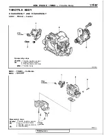
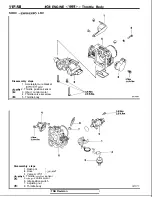
Throttle Bodv
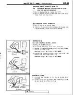
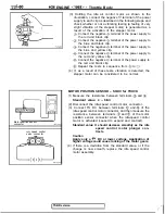
Motor position sensor
connector
speed control
servo connector
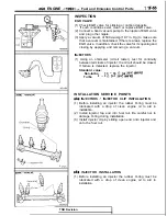
(3) Holding the idle air control motor as shown in the
illustration, connect the negative terminal of the power
supply to each clip as described in the following steps, and
check whether or not a vibrating feeling (a feeling of very
slight vibration of the stepper motor) is generated as a
result of the activation of the stepper motor.
Connect the negative terminal of the power supply to
the red and black clip.
Connect the negative terminal of the power supply to
the blue and black clip.
Connect the negative terminal of the power supply to
the blue and yellow clip.
Connect the negative terminal of the power supply to
the red and yellow clip.
Connect the negative terminal of the power supply to
the red and black clip.
Repeat the tests in sequence from
to
(4) If, as a result of these tests, vibration is detected, the
stepper motor can be considered to be normal.
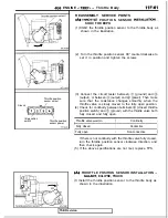
MOTOR POSITION SENSOR SOHC for TRUCK
Measure the resistance between terminals
and
Standard value: 4 6
(2) Disconnect the idle-speed control motor connector.
(3) Connect
DC between terminals
and
of the
idle-speed control motor connector, and then measure the
resistance between terminals
and
of the motor
position sensor connector when the idle-speed control
motor is activated (caused to expand and contract).
Standard value: It should decrease smoothly as the idle
speed control motor plunger con-
tracts.
Caution
Apply only a
DC or lower voltage. Application of
higher voltage could cause locking of the motor gears.
(4) If there is a deviation from the standard value, or if the
change is now smooth, replace the idle speed control
motor assembly.
TSB Revision
,
Summary of Contents for 4G1 series
Page 2: ......
Page 11: ...4Gl ENGINE General Information TSB Revision 1 ...
Page 12: ...VA 4 4Gl ENGINE General Information UBRICATION SYSTEM P 0 Z t7 ii ii I OTJ 09 1 TSB Revision ...
Page 21: ...4Gl ENGINE Special Tools Valve stem seal compressor Flywheel stopper 1 TSB Revision ...
Page 46: ...1 IA 38 461 ENGINE Cvlinder Head and Valves TSB Revision ...
Page 62: ...N O T E S ...
Page 65: ...4G3 ENGINE General Information pqJp3 I 3EN0087 TSB Revision ...
Page 66: ...IIB 4 4G3 ENGINE General Information JBRICATION SYSTEM 3LUOO20 TSB Revision ...
Page 77: ...463 ENGINE Special Tools Removal of crankshaft sprocket 1 TSB Revision ...
Page 106: ...11 B 44 4G3 ENGINE Cylinder Head and Valves 3EN018E TSB Revision ...
Page 127: ...4G6 ENGINE 1992 General Information 6EN0314 TSB Revision I ...
Page 128: ...IIC 4 466 ENGINE 1992 General Information NGlNE SECTIONAL VIEW DOHC TSB Revision ...
Page 129: ...6EN0244 TSB Revision ...
Page 225: ...4G6 ENGINE 1992 Piston and Connecting Rod 1 IC 101 TSB Revision ...
Page 232: ...NOTES ...
Page 235: ...4G9 ENGINE General Information llD 3 ru l 9EN0105 TSB Revision ...
Page 236: ...11D 4 4G9 ENGINE General Information UBRICATION SYSTEM 9EN0106 TSB Revision ...
Page 284: ...NOTES ...
Page 287: ...6G7 ENGINE General Information llE 3 TEN0324 1 Revision ...
Page 289: ...667 ENGINE General Information TSB Revision 7EN0120 I ...
Page 290: ...WE 6 6G7 ENGINE General Information SECTIONAL VIEW DOHC NON TURBO ENGINE TSB Revision 7EN0325 ...
Page 291: ......
Page 292: ...IIE 8 6G7 ENGINE General Information SECTIONAL VIEW DOHC TURBO ENGINE 1 TSB Revision 7EN0335 ...
Page 293: ...667 ENGINE General Information IIE 9 TSB Revision 7EN0334 ...
Page 409: ...4G6 ENGINE 1993 General Information TS8 Revision 6EN0630 ...
Page 411: ...466 ENGINE 1993 General Information 6EN0614 TSB Revision ...
Page 412: ...4G6 ENGINE 1993 General Information ENGINE SECTIONAL VIEW DOHC 6EN0619 TSB Revision ...
Page 413: ...4G6 ENGINE 1993 General Information I W7 6EN0620 TSB Revision ...
Page 522: ...NOTES ...


