


-
64
-
'19 • PAC-SM-334
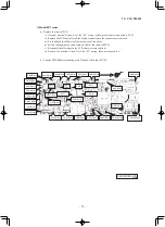
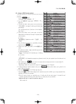
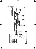
(8) Outdoor unit control failure diagnosis circuit diagram
Model FDC90, 100VNP-W
RD
Ye
llow/Green
YG
Blue
BL
Black
BK
Ye
llow
YE
White
WH
Red
●
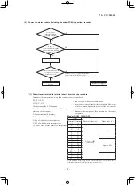
Check point of outdoor unit
CAUTION- HIGH VOLTAGE
High voltage is produced in the control box. Don't touch electrical parts in the control box for 5 minutes after the unitisstopped.
Color symbol
◆
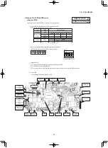
Inspection pow
er transistor
Remove the fasten terminal and test output voltage
◆
Inspection of outdoor fan motor
(Refer to page 103.)
◆
Power source and
serial signal inspection
1 to 2/N :AC220/230/240V 2/N to 3 : Normal if the voltage oscillates between DC 0 and
approx. 20V
L
to
N
: AC 220/230/240V
M
(
BK
)
(
WH
)
(
RD
)
V
W
U
PCB
ASS
Y PCB1
M
MS
TRANSIS
TOR
POWER
POWER
T 1
A
L 250V
CM
FMo
W
V
U
P
N
CNTH
CNEEV
CN
FAN
3
~
+
S.IN
R.IN
G1
N
L
250V 20A
F4
2
N
(
YG
)
C-2
(
RD
)
TB1
TB2
CN20S
(
BK
)
(
WH
)
(
WH
)
(
WH
)
F 3.15
A L
250V
F1
(
BK
)
1
3
(
BK
)
(
WH
)
(
YG
)
(
YG
)
(
RD
)
G2
20S
(
YG
)
(
BK
)
CIRCUIT
~
~
+
-
SWITCHING
CIRCUIT
250V 20A
F8
+
+
PAM
CIRCUIT
PAM
(
YE
)
(
BL
)
T1
T1
1
T2
T12
(
YE
)
(
BL
)
+
~
~
-
L1
L2
EEV
BLOCK
TERMINAL
BLOCK
TERMINAL
F3
t
゜
t
゜
t
゜
TH1
TH2
TH3
2
2
2