

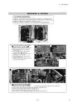


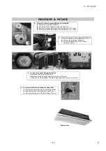


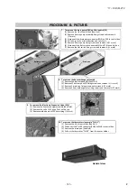


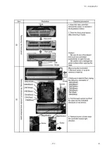


7. To remove the drain pump(DM) and flot switch(FS)
(1) Remove the lid of control box.(See No.1)
(2) Remove 5 drain pump assembly fixing screws and remove it.
(
mark)
(3) Disconnect the drain pump connector(CNR) on PCB in control box.
(4) Pull a hose to the arrow direction and remove it.
(5) Remove 3 drain pump fixing screws and remove it.(
mark)
(6) Disconnect the flot switch connector(CNI) on PCB in control box.
(7) Remove the flot switch fixing screw and remove it.(
mark)
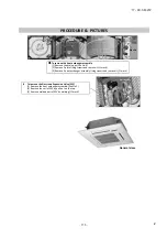
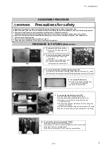
8. To remove the heat exchanger assembly
(1) Remove the bottom panel(B).(See No.3)
(2) Remove 22 bottom panel(F) fixing screws and remove it.(
mark)
(3) Remove 2 drain pan fixing screws and remove it.(
mark)
(4) Remove 4 heat exchanger assy fixing screws and remove it.(
mark)
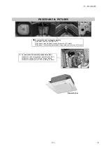
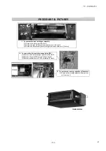
9. To remove the Electronic Expansion Valve (EEV)
(1) Remove the heat exchanger assembly.(See No.8)
(2) Remove the coil of EEV by pull out on the top.
(3) Remove welded part of EEV by welding.(
mark)
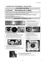
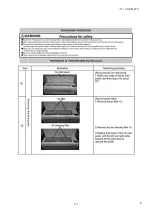
10. To remove the thermistors (example"Thi-R3")
(1) Remove the lid of control box.(See No.1)
(2) Disconnect the Thi-R3 connector(CNN) on PWB in control box.
(3) Remove the drain pan.(See No.8)
(4) Pull out the thermistor"Thi-R3" from the sensor holder.
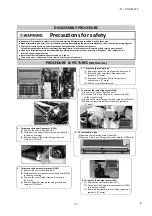
PROCEDURE & PICTURES
Drain pan
Bottom panel(F)
EEV
Coil of EEV
General view
'17 • KX-SM-272
–
1
4
6
–
#
Summary of Contents for 140KXZEN1
Page 153: ... 17 KX SM 272 151 ...
Page 154: ... 17 KX SM 272 152 ...
Page 155: ... 17 KX SM 272 153 ...
Page 156: ... 17 KX SM 272 154 ...
Page 165: ... 163 MEMO 17 KX SM 272 ...