


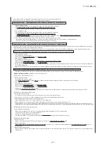


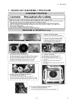


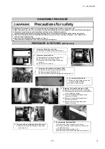


Precautions for safety
Read these "Precautions for safety" carefully before starting disassembly work and do it in the proper way.
When disassembling, be sure to turn off the power. When disassembling the electrical components, check the electrical wiring diagram.
The electrical components are under high voltage by the operation of the booster capacitor.
Fully discharge the capacitor before commencing a repair work. Failure to observe this warning could result in electric shock.
When parts of refrigerant cycle is disassembled by welding, be sure to work after collecting a refrigerant, if the refrigerant isn't
collected, the unit might explode.
Be sure to collect refrigerant without spreading it in the air.
These contents are an example. Please refer to a similar part of actual unit.
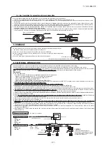
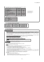
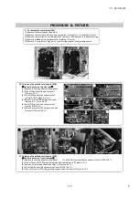
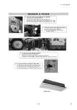
1. To remove the service panel
(1) Remove 5 service panel fixing
screws and remove it.
2. To remove the fan motor (FM)
(1) Remove the service panel.(See No.1)
(2) Disconnect the motor connector(FMxx or CNFxx) on PCB in control box.
(3) Remove 4 fan guard fixing screws and remove it.(
mark)
(4) Remove the propeller fan fixing nut and remove it.(
mark)
(5) Remove 4 fan motor fixing nuts and remove it.(
mark)
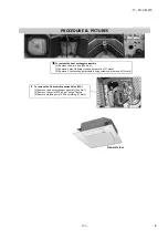
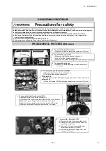
3. To remove the 4-way valve (20S)
(1) Remove the service panel.(See No.1)
(2) Disconnect the coil of 4-way valve connector
(CNNx or CNS,CN20S) on PCB in control box.
(3) Remove the coil of 4-way valve fixing screw
and remove it.(
mark)
(4) Remove welded part of 4-way valve by
welding. (
mark)
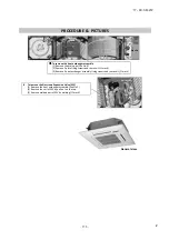
4. To remove the low pressure sensor (PSL)
(1) Remove the service panel.(See No.1)
(2) Disconnect the PSL connector(CNLx or CNPS)
5. To remove the electronic expansion valve (EEV)
on PCB in control box.
(1) Remove the service panel.(See No.1)
(3) Turn PSL to the left and remove it.
(2) Disconnect the EEV connector(CNEEVx) on PCB in control box.
(Double spanners are needed.)
(3) Remove the coil of EEV by pull out on the top.
(4) Remove welded part of EEV by welding.(
mark)
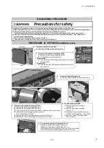
6. To remove the thermistors (example"Tho-D1")
(1) Remove the service panel.(See No.1)
(2) Disconnect the Tho-D1 connector(CNTH) on PCB in control box.
(3) Pull out the thermistor"Tho-D1" from the sensor holder.
7. To remove bypass valve (SV)
(1) Remove the service panel.(See No.1)
(2) Disconnect the SV connector
on PCB in control box.
(3) Remove the coil of SV fixing screws.
(
mark)
(4) Remove 2 coil of SV fixing screws
and remove it.(
mark)
8. To remove the high pressure switch (63H)
(5) Remove welded part of SV by welding.
(1) Remove the service panel.(See No.1)
(2) Disconnect the 63H connector(CNH or CNQx) on PCB in control box.
(3) Remove welded part of high pressure switch by welding.
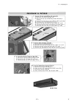
DISASSEMBLY PROCEDURE
PROCEDURE & PICTURES
(FDC
SCM series)
Compressor
4-way valve
Coil of 4-way valve
EEV
Coil of EEV
PSL
6
.
OUTDOOR UNIT DISASSEMBLY PROCEDURE
'17 • KX-SM-272
–
133
–
#
Summary of Contents for 140KXZEN1
Page 153: ... 17 KX SM 272 151 ...
Page 154: ... 17 KX SM 272 152 ...
Page 155: ... 17 KX SM 272 153 ...
Page 156: ... 17 KX SM 272 154 ...
Page 165: ... 163 MEMO 17 KX SM 272 ...