Page 8
MODELS: VS-A50 / WS-A48 / WS-A55 / WS-A65
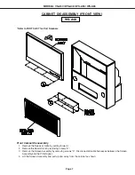
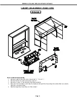
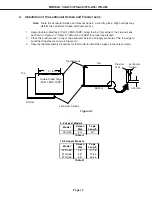
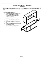
CABINET DISASSEMBLY (REAR VIEW)
Rear Cabinet Disassembly
1.
Remove the Back Board by removing screws "a", “b” and “c”.
2.
Remove the Back Cover by removing screws "e".
3.
Remove 4 screws "d" securing the Light Box Assembly.
4.
Be certain that all cables and connectors between the Light Box Assembly and external items are discon-
nected (e.g. speaker plugs).
5.
Slide the Light Box Assembly out of the cabinet.
WS-A48
Summary of Contents for VS-A50
Page 2: ......
Page 58: ...Page 58 MODELS VS A50 WS A48 WS A55 WS A65 POWER SUPPLY ...
Page 59: ...Page 59 MODELS VS A50 WS A48 WS A55 WS A65 VIDEO COLOR PATH ...
Page 60: ...Page 60 MODELS VS A50 WS A48 WS A55 WS A65 SYNC PATH ...
Page 61: ...Page 61 MODELS VS A50 WS A48 WS A55 WS A65 DEFLECTION HV CIRCUIT ...
Page 62: ...Page 62 MODELS VS A50 WS A48 WS A55 WS A65 X RAY PROTECT ...
Page 63: ...Page 63 MODELS VS A50 WS A48 WS A55 WS A65 HV REGULATION ...
Page 64: ...Page 64 MODELS VS A50 WS A48 WS A55 WS A65 SOUND PATH ...
Page 65: ...Page 65 MODELS VS A50 WS A48 WS A55 WS A65 CONVERGENCE CIRCUIT ...
Page 66: ...Page 66 MODELS VS A50 WS A48 WS A55 WS A65 CONTROL CIRCUIT ...

