Page 18
MODELS: VS-A50 / WS-A48 / WS-A55 / WS-A65
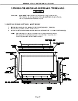
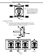
Figure 5-2
Note:
The 4 spring-loaded screws shown
in Fig 5-2 and labeled as "DO NOT
REMOVE", should not be loosened
under any circumstance. Doing so
will break the seal between the
CRT and the CRT-Spacer, causing
leakage of the CRT Coolant.
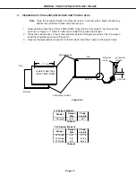
2. Installation of the CRT
Note:
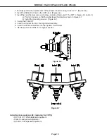
The replacement CRT is supplied as an assembly comprised of the CRT and the
Inner Lens with the space between them filled with ethylene glycol. Care should
be taken during handling and installation to prevent shock from disrupting the seal
or alignment between the CRT and Inner Lens. [Figure 5-3]
Figure 5-3
Figure 5-5
Figure 5-4
Summary of Contents for VS-A50
Page 2: ......
Page 58: ...Page 58 MODELS VS A50 WS A48 WS A55 WS A65 POWER SUPPLY ...
Page 59: ...Page 59 MODELS VS A50 WS A48 WS A55 WS A65 VIDEO COLOR PATH ...
Page 60: ...Page 60 MODELS VS A50 WS A48 WS A55 WS A65 SYNC PATH ...
Page 61: ...Page 61 MODELS VS A50 WS A48 WS A55 WS A65 DEFLECTION HV CIRCUIT ...
Page 62: ...Page 62 MODELS VS A50 WS A48 WS A55 WS A65 X RAY PROTECT ...
Page 63: ...Page 63 MODELS VS A50 WS A48 WS A55 WS A65 HV REGULATION ...
Page 64: ...Page 64 MODELS VS A50 WS A48 WS A55 WS A65 SOUND PATH ...
Page 65: ...Page 65 MODELS VS A50 WS A48 WS A55 WS A65 CONVERGENCE CIRCUIT ...
Page 66: ...Page 66 MODELS VS A50 WS A48 WS A55 WS A65 CONTROL CIRCUIT ...

