


PAGE 43
MODELS: VS-A50 / WS-A48 / WS-A55 / WS-A65
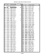
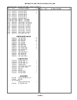
Parts Ordering
To expedite delivery of replacement parts orders, specify the following:
1.
Model Number/Serial Number
2.
Part Number and description
3.
Quantity
Note:
Unless complete information is supplied, delay in processing of orders will result.
Critical and Warranty Parts Designation
Critical Electrical Components
are indicated by
Bold Type
in the Parts List, and in the schematic
diagrams by shading.
Warranty Return Parts
are indicated in the Parts List with an
(*)
.
Parts Tolerance Codes
Refer to the following chart for tolerance characteristics of electrical components.
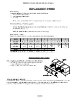
REPLACEMENT PARTS
MARK
B
C
D
F
G
J
K
Tolerance %
± 0.1
± 0.25
± 0.5
± 1
± 2
± 5
± 10
MARK
M
N
V
X
Z
P
Q
Tolerance %
± 20
± 30
± 10
+ 40
- 20
+80
- 20
+100
- 0
+30
- 10
MARK
M
N
V
X
Z
Tolerance (pF)
± 0.1
± 0.25
± 0.5
± 1
± 2
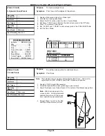
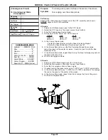
Replacement Part Notes
When Replacing the RF-Switch (RF-SW) or the PCB-SIGNAL:
1. Remove the PLATE-RF SW from the original component,
shown in the diagram at the right.
2. Install the PLATE-RF SW on the new RF-SW.
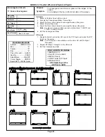
When Replacing the EEPROM
The EEPROMs (IC7C01, IC2K02 and IC8D0) store the adjustment data. After replacing the EEPROM, readjust the
data to the values given in the tables on pages 28 to 30. If good performance is not obtained with these values,
perform the Adjustment Procedure(s) given in the Description and Adjustment columns.
Summary of Contents for VS-A50
Page 2: ......
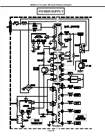
Page 58: ...Page 58 MODELS VS A50 WS A48 WS A55 WS A65 POWER SUPPLY ...
Page 59: ...Page 59 MODELS VS A50 WS A48 WS A55 WS A65 VIDEO COLOR PATH ...
Page 60: ...Page 60 MODELS VS A50 WS A48 WS A55 WS A65 SYNC PATH ...
Page 61: ...Page 61 MODELS VS A50 WS A48 WS A55 WS A65 DEFLECTION HV CIRCUIT ...
Page 62: ...Page 62 MODELS VS A50 WS A48 WS A55 WS A65 X RAY PROTECT ...
Page 63: ...Page 63 MODELS VS A50 WS A48 WS A55 WS A65 HV REGULATION ...
Page 64: ...Page 64 MODELS VS A50 WS A48 WS A55 WS A65 SOUND PATH ...
Page 65: ...Page 65 MODELS VS A50 WS A48 WS A55 WS A65 CONVERGENCE CIRCUIT ...
Page 66: ...Page 66 MODELS VS A50 WS A48 WS A55 WS A65 CONTROL CIRCUIT ...