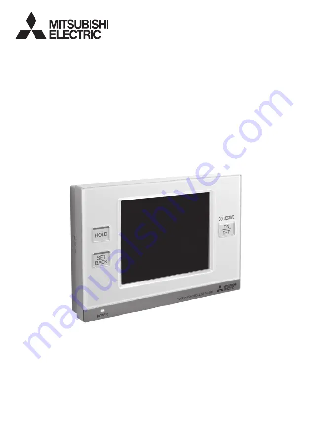
background image

Prior to use, thoroughly read the instructions in this manual to use the product correctly. 

Retain this manual for future reference.

Make sure that this manual and Installation Manual are passed on to any future users.

To ensure safety and proper operation of the unit, the unit should only be installed by 

qualified personnel.

Air Conditioning Control System

TOUCH CONTROLLER

MODEL

TC-24B

Instruction Book

Summary of Contents for TC-24B

Page 1: ...is manual for future reference Make sure that this manual and Installation Manual are passed on to any future users To ensure safety and proper operation of the unit the unit should only be installed by qualified personnel Air Conditioning Control System TOUCH CONTROLLER MODEL TC 24B Instruction Book ...

Page 2: ... is passed on to any future TC 24B users All electric work must be performed by qualified personnel General precautions WARNING Do not install the unit in a place where large amounts of oil steam organic solvents or corrosive gases such as sulfuric gas are present or where acidic alkaline solutions or sprays are used frequently These substances can compromise the performance of the unit or cause c...

Page 3: ...here is a risk of leaking flammable gas If flammable gas accumulates around the controller it may ignite and cause a fire or explosion Properly dispose of the packing materials Plastic bags pose suffocation hazard to children Precautions for moving or repairing the controller WARNING The controller should be repaired or moved only by qualified personnel Do not disassemble or modify the controller ...

Page 4: ...es the functions that are available on the TC 24B Refer to the pages listed for details Function Description Page Unit Operation ON OFF Operation Switches the ON OFF operation of the units such as air conditioning units The LED on the Collective ON OFF button will light up when one or more units are in operation and off when all units are stopped 20 Mode 1 Switches the mode Cooling Drying Fan Auto...

Page 5: ...r LCD touch panel Touch panel displays the operation status of the units Function settings such as weekly schedule settings are accessed through the touch panel The backlight lights up when the panel is touched and lights off after certain period of time The backlight will remain lit as long as an error exists 2 Collective ON OFF button 1 The button allows the user to turn on or off the air condit...

Page 6: ...ove to the Main Menu screen touch the following tab Displays the Main Menu screen 3 To move to the Maintenance screen refer to the Installation Manual GROUP screen LIST screen GRID screen Home screen To the GROUP screen To the GRID screen To the LIST screen To the GRID screen To the Main Menu screen To the Home screen Main Menu screen To the LIST screen To the GROUP screen To the GRID zoom out scr...

Page 7: ... temperature appears between the and buttons e HOLD button Enables Disables the Hold function for the displayed groups Icon appears while the Hold function is enabled f Set Temperature button Setback and Auto dual set point modes Displays the popup window to adjust the set temperature during the Setback and Auto dual set point mode Current room temperature appears above the button Set temperature ...

Page 8: ...tiple Air To Water PWFY units are registered to a group current water temperature on the main Air To Water PWFY unit is displayed Interlocked ventilation LOSSNAY Displays when there are ventilation units interlocked with the air conditioning indoor units in the group General equipment icon Displays the General equipment type Icons GRID zoom out screen ON BG Color blue Group No Check mark Check Wat...

Page 9: ...s interlocked with the air conditioning indoor units General equipment icon Displays the General equipment type GROUP screen Air conditioning unit group Air To Water PWFY group During operation Group No Mode Unit icon Hold Scheduled operation HOLD ON HOLD OFF Error Startup communication error Filter sign Check Water sign Energy saving Interlocked ventilation LOSSNAY Fan speed Air direction Louver ...

Page 10: ...fer to P20 Operation screen GROUP screen for details The number of selected groups 1 The Multiple group selection screen appears The selected groups can be operated collectively Refer to P27 Multiple group selection screen for details Group icon setting 1 appears in the area marked 2 Stops or starts the operation of the air conditioning units through group icon 1 ON OFF operation lock When TC 24B ...

Page 11: ...ng will be especially effective during periods of non occupancy Heat Heat Cool Cool Set temp Setback_Cool Operation pattern during Setback mode The room temperature changes corresponding to the change in the outside temperature Set temp Setback_Heat Room temperature Operation screen GROUP screen Operating the Air conditioning unit group Air To Water PWFY group Air conditioning unit group Air To Wa...

Page 12: ... The temperature is controlled automatically in the Heating ECO mode The user cannot change the temperature settings Booster unit Heating 87 F 122 F 30 C 50 C Heating ECO 87 F 113 F 30 C 45 C Hot Water 87 F 158 F 30 C 70 C Anti freeze 50 F 113 F 10 C 45 C Cooling Invalid Water HEX unit Heating 87 F 113 F 30 C 45 C Heating ECO 87 F 113 F 30 C 45 C Hot Water Invalid Anti freeze 50 F 113 F 10 C 45 C ...

Page 13: ... function are connected only the scheduled operations for this unit will be disabled Refer to the Installation Manual for how to change the Hold type Interlocked ventilation units LOSSNAY Fan speed Air direction Louver settings for Air conditioning unit groups only Touch 4 to show the Interlocked ventilation units LOSSNAY Fan speed Air direction Louver settings screen 4 A C B D A Interlocked venti...

Page 14: ...from other controllers will appear on the buttons and these buttons will not be available for selection If the TC 24B denies other controllers access to itself other controllers cannot disable the functions on the TC 24B If a signal is received to force the Hold setting from other controllers the above icon will appear on the relevant operation button and the button will become unresponsive Operat...

Page 15: ...to mode and backlight timer and group names P50 2 Volume Control Sets the sound volume and screen brightness P54 3 Touch Panel Calibration Calibrates the touch panel P55 4 System Management 1 Status List Displays errors and maintenance signs P56 2 System Changeover Selects the System Changeover setting Automatically switches the entire system to Cooling or Heating based on the room temperature and...

Page 16: ...ate and time setting screen Set the start and end date time Date and time setting screen Daylight saving time setting screen 6 7 6 Touch the 8 Save button The initial date time setting is 1 1 2013 12 00AM If the clock is set forward the operations that were scheduled to have taken place before the new time will be cancelled When the Daylight Saving Time goes in effect the scheduled operations or t...

Page 17: ...tersect to assign a pattern Patterns can be copied pasted or deleted on the Select Group and Days Dates screen e g The weekly schedule of a specific group can be copied and pasted to another group or the schedule pattern of a specific day can be copied and pasted to another day Refer to P37 for details B Setting the operation schedule Main Menu Operation Setting Time and Schedule Set Schedules Typ...

Page 18: ...ted Touch the buttons to check the actions for each scheduled event Refer to P38 Icon Definitions 1 To configure a new pattern using a blank pattern Touch a blank pattern number then touch the button to access the Edit Pattern screen See Step 5 If one or more patterns have been configured and saved the message When copying other setting patterns to edit select the pattern to be copied and touch th...

Page 19: ...he pattern assigned to a specific day or the event that is scheduled to take place at a certain time Multiple items can be deleted at once 2 Touch the Delete button 3 Touch the OK button on the window that pops up 6 Set the time and the actions for the selected event number Auto single set point mode Change values with the buttons Touch the icons repeatedly to select the desired one Setback and Au...

Page 20: ...the buttons to check the actions for each scheduled event Touch the Close button to return to the previous screen 5 To change the schedule settings touch the Return button to return to the Time and Schedule screen and access the Set Schedules screen Inserting an event 1 Touch a row to insert an event above it A red checkmark will appear on the selected row 2 Touch the Insert button A blank row wil...

Page 21: ...k mode will be reflected on each group when the Save button is touched The temperature range that can be set depends on the connected units The cooling and heating set temperatures can be set under the following conditions The cooling set temperature is greater than the heating set temperature The difference between the cooling and heating set temperatures is equal or greater than the minimum temp...

Page 22: ... the 2 Save button To select the groups on which to execute the Hold function 1 Touch the B Hold button on the Collective Operation Setting screen 2 Read the pop up message and touch the OK button to confirm 3 Select the groups to include from the group icons labeled 1 By default all groups are selected 4 Touch the 2 Save button To select the groups on which to execute the Collective ON OFF functi...

Page 23: ...on settings 1 Selecting the functions to be locked and setting the unlock password Main Menu Restriction Settings 1 2 3 Selecting the functions to be locked Main Menu Restriction Settings Lock Buttons 3 Save button Saves the settings 1 Category button 2 Enable Disable Lock button Use these buttons to select the items to be locked when the operation lock button is enabled 1 Touch the 1 Lock Buttons...

Page 24: ... be prohibited from the TC 24B Use the button lock function on the controllers instead If the temperature limits are set too high or low the System Changeover function may not work properly and the units may not operate in the expected mode Cooling or Heating When using the System Changeover function it is recommended not to use the temperature range limit function The DIDO controller groups the L...

Page 25: ...appear or disappear When this function is in use the buttons on TC 24B cannot be disabled from the system controller 3 Locking or unlocking access to the ON OFF Mode Set Temperature Maintenance Sign Reset Air Direction Fan Speed and Timer settings from the local and other system controllers Main Menu Restriction Settings 1 2 3 Main Menu Restriction Settings Prohibit Remote Controller 1 Show Group ...

Page 26: ...on to switch between Show and Hide Example Home screen show hide To set the backlight timeout time Touch the 9 Backlight Timeout Setting button to set the timeout time The back light will go off after a specified time of non use Touch the button repeatedly to select from the following settings 1 min 3 min 5 min 7 min 10 min The backlight will remain lit as long as an error exists Control panel 1 S...

Page 27: ...r the character with the 4 button and then either delete it with the 5 Delete button or overwrite it with a new character 3 When complete touch the 6 OK button to return to the previous screen To change the group name Main Menu Control Panel Display Format Display Format screen 3 3 0 a b c 5 Grouo Name Setting screen 1 Touch the 0 Jump to the group name setting screen button on the Display Format ...

Page 28: ...reen To calibrate the screen properly use a pointy but not sharp object to touch the squares Sharp objects may scratch the touch panel 2 Adjusting the volume and brightness Touch the 2 Volume Control button on the Control Panel screen Main Menu Control Panel 1 2 3 Main Menu Control Panel Volume Control 1 2 3 To adjust the volume 1 Touch the 1 Sound button on the Volume Control screen Every time th...

Page 29: ... Water PWFY groups System Management 1 Checking or resetting the Error or the Maintenance Sign Main Menu System Management Touch the 1 Status List button on the System Management screen 1 2 Main Menu System Management Status List Number of errors Displays the number of errors Group names Displays the name of the group that includes the unit whose Error Filter Signs are turned on 1 Error source add...

Page 30: ...d as the Representative Group will be displayed To designate a different group as the Representative Group select a new group on the screen that appears shown right when the 2 Representative Group button is pressed and then touch the OK button The initial setting for the Representative Group is the group in a specific block with the smallest group number In a group where both Air To Water PWFY and...

Page 31: ...r dealer Refer to P56 Problem is displayed on the screen Solution Touch Main Menu System Management Status List On the Malfunction tab check the error code and the error source address on the screen and consult your dealer Refer to P56 Problem A Filter Sign is displayed on the screen Solution Touch Main Menu System Management Status List On the Maintenance Sign tab check the address on the screen ...

Page 32: ...re range 4 F 158 F 20 C 70 C Humidity 30 90 RH Non condensing Weight 1 1 8 lbs 0 5 kg External dimensions W x H x D 7 3 32 x 4 23 32 x 1 3 16 in 180 x 120 x 30 mm 1 Not for use with a generic DC power supply device Use the power supply unit for transmission line PAC SC51KUA etc by Mitsubishi 2 Power consumption Coefficient is a coefficient to calculate the relative power consumption of the devices...

Page 33: ...harmful interference to radio communications However there is no guarantee that interference will not occur in a particular installation If this equipment does cause harmful interference to radio or television reception which can be determined by turning the equipment off and on the user is encouraged to try to correct the interference by one or more of the following measures Reorient or relocate ...

Reviews: