8
GB
D
F
E
I
NL
P
GR
RU
TR
GB
GB
GB
GB
GB
6. Refrigerant pipe and drain pipe specifications
To avoid dew drops, provide sufficient antisweating and insulating work to the re-
frigerant and drain pipes.
When using commercially available refrigerant pipes, be sure to wind commer-
cially available insulating material (with a heat-resisting temperature of more than
100 °C and thickness given below) onto both liquid and gas pipes.
Be also sure to wind commercially available insulating material (with a form
polyethylene’s specific gravity of 0.03 and thickness given below) onto all pipes
which pass through rooms.
1
Select the thickness of insulating material by pipe size.
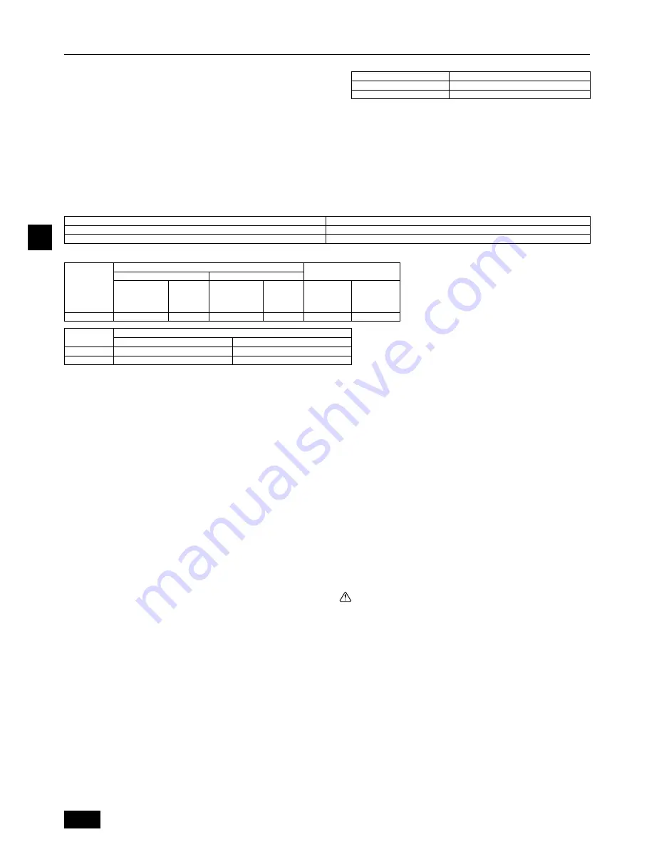
Pipe size
Insulating material’s thickness
6.4 mm to 25.4 mm
More than 10 mm
28.58 mm to 38.1 mm
More than 15 mm
6.1. Refrigerant pipe and drain pipe specifications
[Fig. 6.1.1] (P. 2)
A
Flare cutting dimensions
B
Refrigerant pipe sizes & Flare nut tightening torque
C
Apply refrigerating machine oil over the entire flare seat surface
Copper pipe O.D. (mm)
ø9.52
ø15.88
Flare dimensions øA dimensions (mm)
12.8 – 13.2
19.3 – 19.7
A
Flare cutting dimensions
2
If the unit is used on the highest story of a building and under conditions of
high temperature and humidity, it is necessary to use pipe size and insulating
material’s thickness more than those given in the table above.
3
If there are customer’s specifications, simply follow them.
B
Refrigerant pipe sizes & Flare nut tightening torque
P80, P140
O.D.ø9.52 mm (3/8")
Pipe size
Tightening
torque
(N·m)
34 – 42
O.D.ø15.88 mm (5/8")
Pipe size
Tightening
torque
(N·m)
68 – 82
Liquid pipe
Gas pipe
R410A
O.D. ø9.52 mm (3/8")
O.D. ø9.52 mm (3/8")
P200
P250
R410A
Liquid pipe
Gas pipe
O.D. ø19.05 mm (3/4")
O.D. ø22.2 mm (7/8")
6.2. Refrigerant pipe, drain pipe and filling
port
[Fig. 6.2.1] (P. 3)
Type 80 · 140
Type 200 · 250
A
Air inlet
B
Refrigerant piping (liquid)
C
Refrigerant piping (gas)
D
Control box
E
Drain outlet
F
Air outlet
6.3. Request for refrigerant piping connec-
tion
Connecting refrigerant piping
•
After connecting refrigerant piping, insulate the joints (flared joints) with ther-
mal insulation tubing as shown below.
[Fig. 6.3.1] (P. 3)
Type 80 · 140
A
Thermal insulation tubing
1
B
Caution:
Pull out the thermal insulation on the refrigerant piping at the site, insert the flare
nut to flare the end, and replace the insulation in its original position.
Take care to ensure that condensation does not form on exposed copper piping.
C
Liquid end of refrigerant piping
D
Gas end of refrigerant piping
E
Site refrigerant piping
F
Main body
G
Marked “GAS”
H
Marked “OUTSIDE”
I
Flared insulation (supplied)
2
J
Marked “INSIDE”
K
Thermal insulation
L
Pull
M
Flare nut
N
Return to original position
O
Ensure that there is no gap here
P
Plate on main body
Q
Outside
R
Inside
S
Remove tape
T
Thermal insulation tubing (small) (supplied)
1
U
Tie (large) (supplied)
4
V
Ensure that there is no gap here. Place join upwards.
[Fig. 6.3.2] (P. 3)
Type 200 · 250
A
Thermal insulation tubing
1
B
Caution:
Pull out the thermal insulation on the refrigerant piping at the site, braze the pip-
ing, and replace the insulation in its original position.
Take care to ensure that condensation does not form on exposed copper piping.
C
Refrigerant piping (liquid)
D
Refrigerant piping (gas)
E
Main body
F
Thermal insulation tubing
2
G
Site refrigerant piping
H
Ensure that there are no gaps between the insulation and the main body.
I
Thermal insulation tubing (small) (supplied)
1
J
Ties (large) (supplied)
4
K
Ensure that there is no gap here. Place join upwards.
L
Thermal insulation tubing (medium) (supplied)
2
M
Cut
N
Release gas before removing the brazing.
O
Thermal insulation
P
Pull
Q
Flared pipe end
R
Wrap with damp cloth
S
Return to original position
T
Ensure that there is no gap here.
Caution:
Before removing the brazing, cut off the end of the pipe to release any gas. If
the gas is not released, the pipe may fly off.
1. Remove and discard the rubber bung which is inserted in the end of the unit
piping.
2. Flare the end of the site refrigerant piping.
3. Pull out the thermal insulation on the site refrigerant piping, braze the unit
piping, and replace the insulation in its original position.
*
Before brazing the refrigerant piping,
always wrap the piping on the main
body, and the thermal insulation piping, with damp cloths to prevent heat
shrinkage and burning the thermal insulation tubing.
Take care to ensure
that the flame does not come into contact with the main body itself.
Type
Type
22
29
Liquid
pipe
(mm)
Gas
pipe
(mm)
Flare nut O.D.
WT04313X06_en.p65
2012.8.24, 12:52 PM
8


