background image

44

OCH758

Error information

Error code       A3
Error unit         IU
Time Occurred   
Model name
Serial No.

Reset

Page

2/ 1

Unit#1

4:48

Reset error: Reset button

Error information

Error code       A3
Error unit         IU
Time Occurred   
Model name
Serial No.

Reset

Page

2/ 1

Unit#1

4:48

Reset error: Reset button

Error information

Contact information
       Dealer
              Tel

Reset

Page

Reset error: Reset button

Error reset

Error reset

Main menu:

Error reset

Reset current error?

OK

Cancel

F1

F2

F3

F4

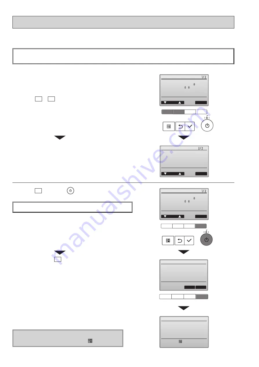
1.  Check code, error unit, refrigerant address, date and time of occur-

rence, model name, and serial number will appear. 

The model name and serial number will appear only if the informa-
tion have been registered.

Press the F1 or F2 button to go to the next page.

When an error occurs, the following screen will appear.
Check the error status, stop the operation, and consult your dealer.

Contact information (dealer's phone number) will appear if 
the information has been registered.

2.   Press  the F4 button or the

button to reset the error 

that is occurring.

Errors cannot be reset while the ON/OFF operation is prohibited.

Select ˝OK˝ with the

F4 button.

Navigating through the screens

• To go back to the Service menu .......... [ 


]


button

13-2. ERROR INFORMATION

blinks

F1

F2

F3

F4

blinks

F1

F2

F3

F4

Summary of Contents for Mr.Slim PKA Series

Page 1: ...REMOTE CONTROLLER 36 Indoor unit Model Name Service Ref PARTS CATALOG OCB758 INDOOR UNIT PKA M35LA PKA M35LA ER PKA M35LA ET PKA M50LA PKA M50LA ER PKA M50LA ET PKA M35LAL PKA M35LAL ER PKA M35LAL ET PKA M50LAL PKA M50LAL ER PKA M50LAL ET SPLIT TYPE HEAT PUMP AIR CONDITIONERS SPLIT TYPE AIR CONDITIONERS No OCH758 December 2020 R32 R410A PKA M35LA TH PKA M35LA ER TH PKA M35LA ET TH PKA M50LA TH PKA...

Page 2: ...A PUZ M100YKA PUZ M140YKA OCH707 OCB707 PUHZ ZRP35 50VKA2 PUHZ ZRP71VHA2 PUHZ ZRP35 50VKA2 ER ET PUHZ ZRP71VHA2 ER ET OCH635 OCB635 PUHZ ZRP100VKA3 PUHZ ZRP140VKA3 PUHZ ZRP100YKA3 PUHZ ZRP140YKA3 PUHZ ZRP100VKA3 UK PUHZ ZRP140VKA3R1 UK PUHZ ZRP100YKA3R1 UK PUHZ ZRP140YKA3R2 UK OCH645 OCB645 PUHZ ZRP200YKA3 PUHZ ZRP200YKA3 OCH680 OCB680 PUHZ P200YKA3 PUHZ P200YKA3 UK OCH679 OCB679 PUHZ P100 140VKA ...

Page 3: ...auge Gauge manifold Torque wrench Gas leak detector Charge hose Tools for R32 R410A Contamination inside refrigerant piping can cause deterio ration of refrigerant oil etc In case of reconnecting the refrigerant pipes after detaching make the flared part of pipe re fabricated Ventilate the room if refrigerant leaks during operation If refrigerant comes into contact with a flame poisonous gases wil...

Page 4: ... pipes 12 When performing brazing work be sure to ventilate the room sufficiently Make sure that there are no hazardous or flammable materials nearby When performing the work in a closed room small room or similar location make sure that there are no refriger ant leaks before performing the work If refrigerant leaks and accumulates it may ignite or poisonous gases may be released 13 Do not install...

Page 5: ...he Refrigeration Equipment Where electrical components are being changed they shall be fit for the purpose and to the correct specification At all times the manufacturer s maintenance and service guidelines shall be followed If in doubt consult the manufacturer s technical department for assistance The following checks shall be applied to installations using flammable refrigerants The charge size ...

Page 6: ... procedures shall be used However for flammable refrigerants it is important that best practice is followed since flammability is a considera tion The following procedure shall be adhered to remove refrigerant purge the circuit with inert gas evacuate purge again with inert gas open the circuit by cutting or brazing The refrigerant charge shall be recovered into the correct recovery cylinders For ...

Page 7: ...to cylinders ensure that only appropriate refrig erant recovery cylinders are employed Ensure that the correct number of cylinders for holding the total system charge are available All cylinders to be used are designated for the recovered refrigerant and labelled for that refrigerant i e special cylinders for the recovery of refrigerant Cylinders shall be complete with pressure relief valve and as...

Page 8: ...ressure performance of 5 09MPa G or over 3 Electronic weighing scale 4 Gas leak detector Use the detector for R32 or R410A 5 Adaptor for reverse flow check Attach on vacuum pump 6 Refrigerant charge base 7 Refrigerant cylinder Top of cylinder R32 or R410A refrigerant Cylinder with syphon 8 Refrigerant recovery equipment Electronic weighing scale Unit Filter Air intake Vane Air outlet Louver Front ...

Page 9: ...unsell 1 0Y 9 2 0 2 Heat exchanger Plate fin coil Fan Fan drive No Line flow fan direct 1 Fan motor output kW 0 030 Airflow Lo Mid2 Mid1 Hi m3 min CFM 7 5 8 2 9 2 10 9 External static pressure Pa mmAq 0 direct blow Booster heater kW Operation control Thermostat Wireless remote controller built in Noise level Lo Mid2 Mid1 Hi dB 34 37 40 43 Field drain pipe O D mm inch 16 5 8 Dimensions W mm inch 89...

Page 10: ...dle2 Middle1 High 1 0m 1 0m Measurement location Model Wall Main unit 5 1 SOUND LEVELS 5 2 NOISE CRITERION CURVES 10 20 30 40 50 60 70 80 90 63 125 250 500 1000 2000 4000 8000 High FAN Medium 2 Medium 1 LINE Low OCTAVE BAND SOUND PRESSURE LEVEL dB 0dB 0 0002μbar Approximate minimum audible limit on continuous noise BAND CENTER FREQUENCIES Hz ...

Page 11: ...11 OCH758 Unit mm OUTLINES AND DIMENSIONS 6 ...

Page 12: ...OCH758 12 WIRING DIAGRAM 7 ...

Page 13: ...50 Thermistor TH5 Cond Eva temperature Thermistor TH1 Room temperature Refrigerant flow in cooling Refrigerant flow in heating Strainer 50 Strainer 100 Heat exchanger Refrigerant GAS pipe connection Flare Refrigerant LIQUID pipe connection Flare REFRIGERANT SYSTEM DIAGRAM 8 13 ...

Page 14: ...certain the cause of the trouble according to 9 4 TROUBLESHOOTING OF PROBLEMS The trouble is not reoccurring Logged 1Consider the temporary defects such as the work of protection devices in the refrigerant circuit including compressor poor connection of wiring noise etc Re check the symptom and check the installation environment refrigerant amount weather when the trouble occurred matters related ...

Page 15: ...lamp blinks Number of times Check code 1 P1 Intake sensor error 2 P2 Pipe TH2 sensor error P9 Pipe TH5 sensor error 3 E6 E7 Indoor outdoor unit communication error 4 P4 Drain sensor error Float switch connector CN4F open 5 P5 Drain pump error PA Forced compressor stop due to water leakage abnormality 6 P6 Freezing Overheating protection operation 7 EE Combination error between indoor and outdoor u...

Page 16: ...Only LED 1 is lit LED 1 2 blink Connector for the outdoor unit s protection device is not connected Reverse or open phase wiring for the outdoor unit s power terminal block L1 L2 L3 Display messages do not appear even when operation switch is turned ON operation lamp does not light up Only LED 1 is lit LED 1 blinks twice LED 2 blinks once Incorrect wiring between indoor and outdoor units incorrect...

Page 17: ...ard 1 3 Check resistance value of thermistor For characteristics refer to P1 above 2 Check contact failure of connector CN44 on the indoor controller board Refer to 9 7 TEST POINT DIAGRAM Turn the power on and check restart after inserting connector again 4 Check pipe liquid temperature with remote controller in test run mode If pipe liquid temperature is extremely low in cooling mode or high in h...

Page 18: ...ive indoor fan motor Fan motor is defective Indoor controller board is defec tive 5 Defective outdoor fan control 6 Overcharge of refrigerant 7 Defective refrigerant circuit clogs 8 Bypass circuit of outdoor unit is defective Cooling or drying mode 1 Check clogs of the filter 2 Remove shields 4 Refer to 9 6 HOW TO CHECK THE PARTS 5 Check outdoor fan motor 67 Check operating condition of refrigeran...

Page 19: ...one of the remote controllers main if there is no problem with the action above 3 Check wiring of remote controller Total wiring length maximum 500 m Do not use cable with 3 or more cores The number of connecting indoor units maximum 16 units The number of connecting remote control ler maximum 2 units When it is not the above mentioned problem of 1 3 4 Diagnose remote controllers a When OK is disp...

Page 20: ...to transmit signals Indoor controller board Abnormal if data cannot be read normally from the nonvolatile memory of the indoor controller board 1 Defective indoor controller board 1 Replace indoor controller board The check code in the parenthesis indicates PAR 40MAA model Remote controller control board 1 Abnormal if data cannot be read nor mally from the nonvolatile memory of the remote controll...

Page 21: ...t switch 4 Contact failure of float switch connector 5 Dew condensation on float switch Drain water trickles down lead wire Drain water ripples due to filter clogging 6 Extension piping connection difference at twin triple or quadruple system 7 Miswiring of indoor outdoor connecting at twin triple or quadruple system 8 Room temperature thermistor liquid pipe temperature thermis tor detection is de...

Page 22: ...onnecting wire for miswiring When 220 240 V AC is detected check 4 below 4 Check the fuse on indoor controller board Check the wiring connection If no problem is found indoor controller board is defective 1 Check the voltage of indoor power supply terminal block L N When 220 240 V AC is not detected check the power supply wiring When 220 240 V AC is detected check 2 below 2 Check that there is no ...

Page 23: ...ilure 1 Check the connection of remote con troller wires in case of twin triple indoor unit system When 2 or more indoor units are wired in one refrigerant system connect remote controller wires to one of those units 2 Check the setting of refrigerant address in case of grouping control system If there are some units whose refrigerant addresses are 0 in one group set one of the units to 0 using SW...

Page 24: ...rain up machine during self diagnosing 2 Emergency Operation becomes continuous only by switching the power source on off ON OFF on the remote control or temperature control etc does not function 3 Avoid operating for a long time when the outdoor unit begins defrosting while Emergency Operation of the heating is activated because it will start to blow cold air 4 Emergency cooling should be limited...

Page 25: ...mistor liquid TH2 Condenser evaporator temperature thermistor TH5 Disconnect the connector then measure the resistance with a multimeter Refer to 9 6 1 Thermistor Vane motor MV Sky Blue Sky Blue Red Sky Blue 7 9 10 6 8 Connector CNV pin No M Sky Blue Measure the resistance between the terminals with a multimeter At the ambient temperature 25 C Normal 0 9 Red Sky Blue 0 8 Red Sky Blue 0 7 Red Sky B...

Page 26: ...ng of SWE Set SWE to OFF if it is set to ON Is there contact failure Is the voltage normal Does the voltage repeat 0 V DC and 15 V DC Indoor controller board fuse check Wiring contact check Contact of fan motor connector CNMF Power supply check Remove the connector CNMF Measure the voltage in the indoor controller circuit board TEST POINT 1 VDC between 1 and 4 of the fan connector VDC 310 340 V DC...

Page 27: ...E 3 15 A 250 V CN3C Transmission Indoor outdoor 0 28 VDC CN44 Pipe temperature thermistor 1 2 Liquid TH2 3 4 Condenser Evaporator TH5 CN90 Connect to the remote operation adapter CN22 Connect to the terminal block TB5 Remote controller connecting wire option CNRU Connect to SWITCH BOARD S B LED BOARD L B and PCB for WIRELESS REMOTE CONTROLLER option CN20 Room temp thermistor TH1 CNV Vane motor MV1...

Page 28: ... number settings are supported The pair number settings of the wireless remote controller and indoor control PCB J41 J42 are given in the table on the left in the table indicates the jumper wire is dis connected MODELS SETTING PKA M LA L MODELS SETTING PKA M35LA L PKA M50LA L ON OFF 1 2 3 4 5 6 6 6 ON OFF 1 2 3 4 5 ON OFF 1 2 3 4 5 Jumper wire Short Open The black square indicates a switch positio...

Page 29: ...ting the unit number to Grp Refer to the service manual that comes with each outdoor unit 2 Functions available when setting the unit numbers to 1 4 or All 07 in case of wireless remote controller Function Settings Mode No Setting No Initial setting Setting Filter sign 100 Hr 07 1 2500 Hr 2 No filter sign indicator 3 Fan speed Silent 08 1 Standard 2 High ceiling 3 Fan speed during the cooling ther...

Page 30: ...function and Back up function Outline of functions Main and sub unit operate alternately according to the interval of rotation setting Main and sub unit should be set by refrigerant address Outdoor DIP switch setting Refrigerant address 00 Main unit Refrigerant address 01 Sub unit When an error occurs to one unit another unit will start operation Back up function System constraint This function is...

Page 31: ... OFF Monitoring the request code of current setting Setting contents Rotation ON Alternating interval 28days and back up function Rotation ON Alternating interval 14days and back up function Rotation ON Alternating interval 1day and back up function Back up function only No 5 324 Rotation ON Alternating interval 7days and back up function Rotation ON Alternating interval 5days and back up function...

Page 32: ...crew 3 Disconnect the indoor outdoor connecting wire from terminal block TB4 4 Disconnect the wired remote controller connecting wire from terminal block TB5 LAL model Optional parts 5 Disconnect the connectors on the indoor controller board 6 Disconnect the connector for ground wire 7 Remove the screw on lower side of the electrical box See Photo 3 8 Push up the upper fixture catch to remove the ...

Page 33: ...E and VANE MOTOR AND DRAIN HOSE 1 Remove the panel and corner box Refer to procedure 1 2 Remove the electrical box covers Refer to procedure 2 3 Disconnect the vane motor connector CNV on the indoor controller board 4 Push fixture and pull out the drain hose from the nozzle assembly and remove nozzle assembly See Photo 6 Photo 4 Photo 5 Photo 6 5 REMOVING THE VANE MOTOR 1 Remove the nozzle assembl...

Page 34: ...ne flow fan to the lower left When attaching the line flow fan screw the line flow fan so 4mm gap is provided between the right end of the line flow fan and the right wall of the air passage of the box Photo 9 Photo 8 7 REMOVING THE PIPE TEMPERATURE THERMISTOR LIQUID TH2 AND COND EVA TEMP THERMISTOR TH5 1 Remove the panel and the corner box Refer to proce dure 1 2 Remove the electrical box covers ...

Page 35: ... to procedure 6 6 Remove 2 screws fixing the left side of the heat exchanger See Photo 10 7 Remove the heat exchanger 9 REMOVING THE ROOM TEMPERATURE THERMISTOR 1 Remove the panel and corner box Refer to procedure 1 2 Remove the electrical box covers Refer to procedure 2 3 Remove the room temperature thermistor 4 Disconnect the connector CN20 on the indoor controller board Photo 12 Photo 13 Room t...

Page 36: ...tion except for the ON OFF button 6 ON OFF lamp This lamp lights up in green while the unit is in operation It blinks while the remote controller is starting up or when there is an error 7 Function button F1 Main display Press to change the operation mode Menu screen The button function varies with the screen 8 Function button F2 Main display Press to decrease temperature Main menu Press to move t...

Page 37: ...ol Set temp Auto Basic mode Fri Cool Mode Temp Fan Set temp Auto 2 1 5 6 7 8 9 0 1 3 9 4 2 3 4 5 6 7 2 1 5 Display 4 3 8 4 Appears when the Weekly timer is enabled 5 Appears while the units are operated in the energy saving mode Will not appear on some models of indoor units 6 Appears while the outdoor units are operated in the silent mode 7 Appears when the built in thermistor on the remote contr...

Page 38: ... vane angle ON OFF timer Auto return Clock Main Sub Temp range Auto OFF timer Schedule Daylight saving time Clock Administrator password Operation locked 3D i See sensor High power Vane Louver Vent Lossnay Comfort Timer Energy saving Basic setting Display setting Operation setting Restriction Weekly timer OU silent mode Timer menu Main display Display details Contrast Brightness Language selection...

Page 39: ...run Model name input Function setting Error history Maintenance password Dealer information input Error information Test run menu Maintenance information Filter information Cleaning Settings menu Check menu Other menu Auto descending panel Descending operation Self check Descending adjustment Remote controller check Continue from the previous page Not all functions are available on all models of i...

Page 40: ...tdoor units over temperature control Set the Start Stop times for each day of the week Select the desired silent level from Normal Middle and Quiet Night setback 1 Use to make Night setback settings Select Yes to enable the setting and No to disable the setting The temperature range and the start stop times can be set Energy saving Restriction Temp range 2 Use to restrict the preset temperature ra...

Page 41: ...ayed The model name manufacturing number and contact information need to be registered in advance to be displayed Filter information Use to check the filter status The filter sign can be reset Cleaning Auto descending panel Use to lift and lower the auto descending panel Optional parts Service Test run Select Test run from the Service menu to bring up the Test run menu Test run Drain pump test run...

Page 42: ...ignal transmitted from the remote controller has been received Signals can be received up to approximately 7 meters in a direct line from the indoor unit in an area 45 to the left and right of the unit However illumination such as fluorescent lights and strong light can affect the ability of the indoor unit to receive signals If the operation lamp near the receiver on the indoor unit is blinking t...

Page 43: ...ing Auto Set Temperature buttons Weekly timer ON OFF button Set Time button Sets the time Airflow button Changes up down airflow direction Mode button Changes operation mode Timer ON button Timer OFF button OFF ON button Fan Speed button Changes fan speed SET SEND button CANCEL button Up Down buttons Menu button i see button Reset button Remote controller display Transmission area 3D i See sensor ...

Page 44: ...e of occur rence model name and serial number will appear The model name and serial number will appear only if the informa tion have been registered Press the F1 or F2 button to go to the next page When an error occurs the following screen will appear Check the error status stop the operation and consult your dealer Contact information dealer s phone number will appear if the information has been ...

Page 45: ...ormation Filter information Cleaning While no errors are occurring page 2 2 of the error information can be viewed by selecting Error information from the Maintenance menu Errors cannot be reset from this screen Checking the error information F1 F2 F3 F4 ...

Page 46: ...ntenance password is required 3 If the password matches the Service menu will appear The type of menu that appears depends on the connected indoor units type A screen will appear that indicates the setting has been saved Navigating through the screens To go back to the Service menu button To return to the previous screen button Note The initial maintenance password is 9999 Change the default passw...

Page 47: ...utton to go through the operation modes in the order of Cool and Heat Check the auto vane with the F1 F2 buttons Press the button to return to Test run operation Press the button When the test run is completed the Test run menu screen will appear The test run will automatically stop after 2 hours The function is available only for the model with vanes Test run operation Auto vane check Press the b...

Page 48: ... from the unit 6 Press the VANE button and check whether the auto vane operates properly 7 Press the ON OFF button to stop the test run Note Point the remote controller towards the indoor unit receiver while following steps 2 to 7 It is not possible to run in FAN DRY or AUTO mode 1 A B 2 3 13 4 3 PAR SL100A E 1 Press the button 1 to stop the air conditioner If the weekly timer is enabled is on pre...

Page 49: ...t is common or when running all units all indoor units for the se lected refrigerant address will start fan operation Function setting Ref address Sending data 5 When the settings are completed press the button to send the setting data from the remote controller to the indoor units When the transmission is successfully completed the screen will return to the Function setting screen Note Make the a...

Page 50: ... toward the receiver of the indoor unit and press the h button 3 Set the unit number Press the TEMP button to set the unit number Press 01 to specify the indoor unit whose unit number is 01 Direct the wireless remote controller toward the receiver of the indoor unit and press the min button Notes 1 If a unit number that cannot be recognized by the unit is entered 3 beeps of 0 4 seconds will be hea...

Page 51: ...de number B Fig 3 Direct the wireless remote controller toward the receiver of the indoor unit and press the button Current setting number 1 1 beep 1 second 2 2 beep 1 second each 3 3 beep 1 second each 4 Selecting the setting number Use the button to change the Setting number C Fig 4 Direct the wireless remote controller toward the receiver of the indoor unit and press the button 5 To select mult...

Page 52: ...press the button Select Check with the F1 or F2 button and press the button 3 16 error history records will appear 4 records are shown per page and the top record on the first page indicates the latest error record To delete the error history press the F4 button Delete on the screen that shows error history A confirmation screen will appear asking if you want to delete the error history Press the ...

Page 53: ...ute will appear will appear if no error history is available 4 Resetting the error history Press the F4 button Reset on the screen that shows the error history A confirmation screen will appear asking if you want to delete the error history Press the F4 button OK to delete the error history If deletion fails Request rejected will appear Unit not exist will appear if no indoor units that are corres...

Page 54: ...ET address B indoor unit and the number of blinks of the OPERATION INDICATOR lamp check is completed f 13 7 3 PAR SL100A E Procedure 1 Press the CHECK button twice CHECK lights and refrigerant address 00 blinks Check that the remote controller s display has stopped before continuing 2 Press the TEMP buttons Select the refrigerant address of the indoor unit for the self diagnosis Note Set refrigera...

Page 55: ...32 There is noise on the transmission line or the indoor unit or another remote controller is faulty Check the transmission line and the other remote controllers NG ALL0 ALL1 Send receive circuit fault The remote controller needs replac ing ERC The number of data errors is the discrepancy between the number of bits in the data transmitted from the remote controller and that of the data that was ac...

Page 56: ... the button Fixed operation will start Note Stable mode will take approx 20 minutes F1 F2 F3 F4 Check menu Cursor Service menu Error history Diagnosis Smooth maintenance Request code Smooth maintenance Return Smooth maintenance Return Smooth maintenance Return Page Page Page COMP current COMP run time COMP On Off COMP frequency A Hz Hr times Hr Ref address Cool Ref address Cool Ref address Cool Su...

Page 57: ... 01 Outdoor unit Indoor unit 01 Outdoor unit Indoor unit 01 Remote controller Details on the operation data including each thermistor temperature and error history can be confirmed with the remote controller Select Request code with the F1 or F2 button and press the button Select Check with the F1 or F2 button and press the button 2 Set the Refrigerant address and Request code Select the item to b...

Page 58: ...ICE TOKYO BUILDING 2 7 3 MARUNOUCHI CHIYODA KU TOKYO 100 8310 JAPAN CCopyright 2020 MITSUBISHI ELECTRIC CORPORATION Published Dec 2020 No OCH758 Made in Japan Specifications are subject to change without notice ...

Reviews: