


3-77
Parallel I/O unit
3 Controller
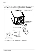
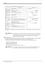
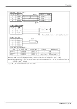
■ Installation method
The expansion parallel input/output unit is installed outside of the controller. Connect with the network
connection cable (NETcable-1) from the RIO connector in the rear/into of the controller.(Terminator is connected
at the time of shipment)
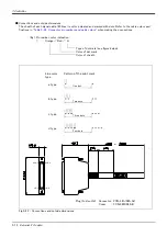
Fig.3-25 : Installing the parallel I/O unit (CR1DA-700/CR1DA-700-S15)
6 0
5 4
6
放熱
、配
線余裕
150
6
156
2 - M 5 ネ ジ
6
168
放熱
余裕
1 2 8
(1 7 5 )
10
0
天
配 線 余 裕
(4 0 )
地
< 2 A - R Z 3 6 1 >
制 御 盤 取 付 寸 法
2 A - R Z 3 6 1 の 取 付 寸 法
6
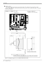
<CR1DA-771/CR1DA-771-S15>
RIOコネクタ
コントローラ背面
Controller rear
upside
downside
Wiring space
H
e
at
rad
ia
ti
on
sp
ace
Ra
diation/
wiring spac
e
2-M5 screw
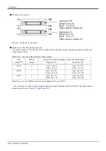
Control panel installation dimensions
Installation dimensions of 2A-RZ361/371 (The controller outside installation)
* The figure is CR1DA-771.
(CR1DA-771-S15 is the same.)


