3
)
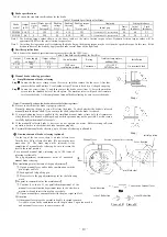
Brake specifications
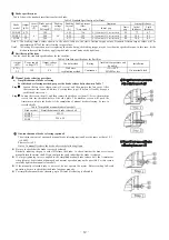
Table 5 shows the standard specifications for the brake.
Table 5 Standard Specifications for Brake
Brake
model
Output
(kW)
Number
of poles
(P)
Brake power
supply
Voltage(V)
Braking
voltage
DC(V)
Braking
Current
(A)
Braking torque
(Nm)
*Note 1 and
2
Gap(mm) Lining
thickness
Initial gap
Limit
gap
Initial
thickness
Limit
thickness
SNB 0.8
0.75
4
200
90
0.24 7.16
0.15(inserted)-0.25 (not inserted)
0.5 7.7 6.7
SNB1.5 1.5
200
0.25 14.3
0.20(inserted)-0.30 (not inserted)
0.5 10.0 8.5
SNB2 2.2
200
0.37 21.0
0.20(inserted)-0.30 (not inserted)
0.5 10.0 8.5
Note
1: The braking torque values shown in the above table are the static friction torque values. Dynamic friction torque values will be
approximately 80% of the static friction torque values.
Note2:
At starting first operation or after replacing the brake lining, the braking torque may be less than the specified torque. In this case, fit the
friction surfaces of the brake by applying the brake several times with a light load
4
)
Rectifier specifications
Table6 shows the standard specifications for the rectifier .
Table6 Standard specifications for Rectifier
Output
(kW)
Power supply
voltage (V)
Output voltage
DC(V)
Control method
Rating
Ambient temperature and
humidity
Installation
0.75
~
2.2
200 90
Half wave
rectification method
Continuous
-15
~
+40°C
90%RH or less
On terminal block
.
5
)
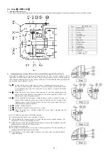
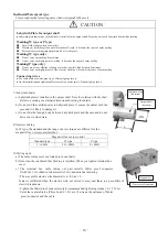
Manual brake releasing procedure
a)
Simplified manual brake releasing
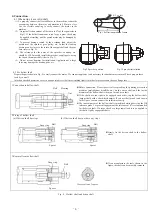
For this brake releasing method, prepare the brake release bolts shown in Table 7
Step
1
Loosen the fan cover clamp screws (4 screws), and then remove the fan cover. After
that, remove the fan and End-face V seal(outdoor type). (The fan is fixed by hexagon
socket head setscrews.)
Step
2
Loosen the screws (item 3), and then remove the brake cover (item 1). Screw the machine
screws into the threaded holes of the side plate. The machine screws will push the
Armature to release the brake. At the completion of manual brake releasing, be sure to
reset the brake.
Table 7 Simplified manual brake release bolt
Brake model
Simplified manual brake release bolt
SNB0.8 M4×25
SNB1.5
M6
x
40
SNB2
b
)
One-touch manual brake releasing (optional)
The written contents of one-touch manual brake releasing(optional) are the same as that of 0.1
~
0.4kW.
Please refer to P9
Notes: To manually release the brake, observe the following items:
Be sure to check that the brake is properly released.
Basically, reducing the gap to zero will release the brake. To check whether the brake is released,
manually turn the motor shaft. If you can turn the shaft, judge that the brake is released.
If a large tightening force is applied to the simplified manual brake release bolt, the Armature or
side plate may be distorted or damaged, and normal operation may not be possible. For this reason,
carefully tighten the manual release bolt.
If the manually released brake is not reset, do not operate the motor. Before starting full-scale
operation, be sure to check that the brake functions properly.
For simplified manual brake releasing, up to 50 times of releasing is allowable.
a)Simplified manual brake
releasing(pattern 1)
b)Simplified manual brake
releasing(pattern 2)
- 12 -
Summary of Contents for GM-SHY
Page 1: ......
Page 2: ......
Page 20: ... 18 ...
Page 21: ... 19 ...
Page 22: ... 20 ...
Page 23: ......
Page 24: ......

