3
)
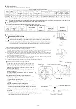
Brake specifications
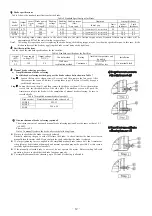
Table3 shows the standard specifications for the brake.
Table 3 Standard Specifications for Brake
Brake
model
Output
(kW)
Number
of poles
(P)
Brake power
supply
Voltage(V)
Braking
voltage
DC(V)
Braking
Current
(A)
Braking torque
(Nm)
*Note 1 and 2
Gap(mm)
Lining thickness
Initial gap
Limit
gap
Initial
thickness
Limit
thickness
SBM 80
0.1,0.2
4
200
90
0.16
1.91
0.15(inserted)-0.25 (not inserted)
0.4 6.0 5.3
SNB 0.4
0.4
4
200
90
0.18
3.82
0.15(inserted)-0.25 (not inserted)
0.4 5.9 4.9
Note
1: The braking torque values shown in the above table are the static friction torque values. Dynamic friction torque values will be
approximately 80% of the static friction torque values.
Note 2: At starting first operation or after replacing the brake lining, the braking torque may be less than the specified torque. In this case, fit the
friction surfaces of the brake by applying the brake several times with a light load
4
)
Rectifier specifications
Table 4 shows the standard specifications for the rectifier (for the 200V type).
Table 4 Standard specifications for Rectifier
Output
(kW)
Power supply
voltage (V)
Output voltage
DC(V)
Control method
Rating
Ambient temperature
and humidity
Installation
0.1,0.2 200
90
Half wave
rectification method
Continuous
-15
~
+40°C
90%RH or less
On terminal block
0.4 200
90
5
)
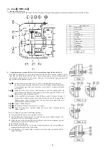
Manual brake releasing procedure
a)
Simplified manual brake releasing
Step
1
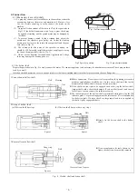
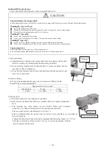
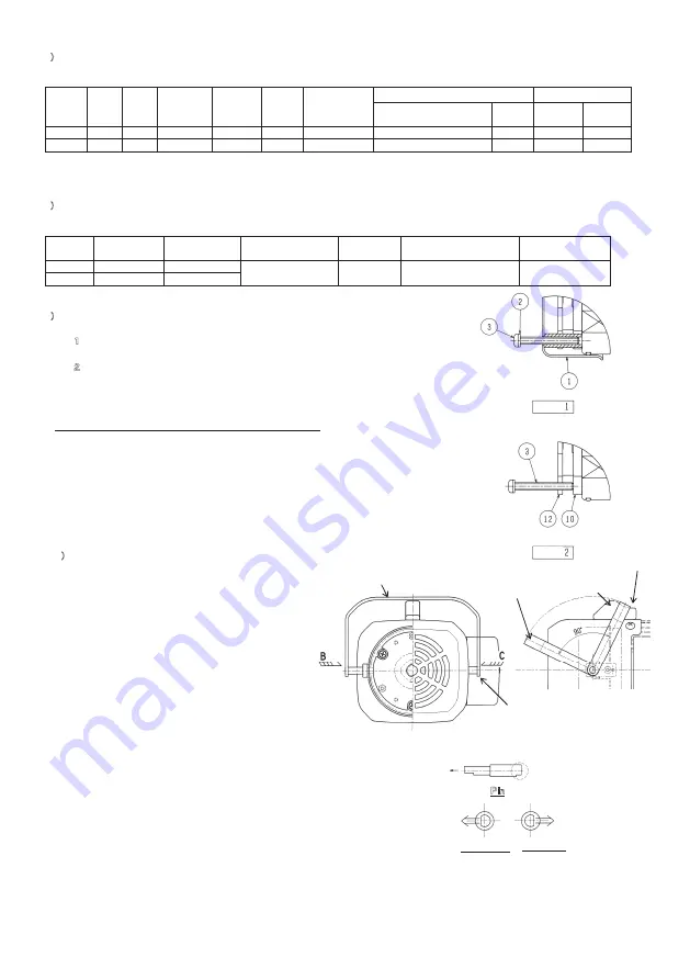
Loosen the fan cover clamp screws (4 screws), and then remove the fan cover. After that,
remove the fan and End-face V seal.(outdoor type)
;
The fan is fixed by a C-shaped snap ring.
Step
2
Loosen the screws (item 3), and then remove the brake cover (item 1). Screw the machine
screws into the threaded holes of the side plate. The machine screws will push the Armature
to release the brake. At the completion of manual brake releasing, be sure to reset the brake.
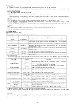
Notes: To manually release the brake, observe the following items:
Be sure to check that the brake is properly released.
Basically, reducing the gap to zero will release the brake. To check whether the brake is released,
manually turn the motor shaft. If you can turn the shaft, judge that the brake is released.
If a large tightening force is applied to the simplified manual brake release bolt, the Armature or
side plate may be distorted or damaged, and normal operation may not be possible. For this reason,
carefully tighten the manual release bolt.
If the manually released brake is not reset, do not operate the motor. Before starting full-scale
operation, be sure to check that the brake functions properly.
For simplified manual brake releasing, up to 50 times of releasing is allowable.
b
)
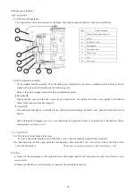
One-touch manual brake releasing (optional)
・
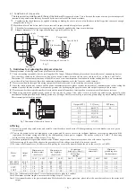
On the top of the fan cover, there is a brake release lever.
Turn the lever 90°to release the brake. (Do not turn the lever
more than 90°. The brake may not be released.) At the
completion of manual brake releasing, be sure to return the
lever to the initial position.
・
.For one-touch manual brake releasing, up to 100 times of
releasing is allowable.
The gap adjustment (maintenance) point of one-touch
manual brake releasing
【
The resolution point at the time of the gap adjustment
】
①
Open a manual lever and exclude combination with the
pin of right and left.
②
Each right and left pulls up pin.
③
Please refer to the gap adjustment point for the following
work.
【
The point to reassemble after the maintenance
】
①
Confirm it so that a D cut parallelism department of the
manual lever combination department turns to the slowdown
machine side and insert it from a fan cover hole.
②
Open a manual lever and combined with the pin of right and left.
※
Attention
Of the manual lever please be careful to be able to spread too much.
A wobble occurs in the combination with the pin when I open too much it,
and a manual lever is easy to come to come off.
Step
Step
initial position
Position of manual lever releasing
Manual lever
Lever fixation
pin
(
Both side
)
Pin
View of B
View of C
side of Reduction
side of Reduction
Insert direction
Connection of manual
lever
- 10 -
Summary of Contents for GM-SHY
Page 1: ......
Page 2: ......
Page 20: ... 18 ...
Page 21: ... 19 ...
Page 22: ... 20 ...
Page 23: ......
Page 24: ......

