Mitsubishi Electric FX5U Series Training Manual Download Page 41

Cutting or copying a ladder

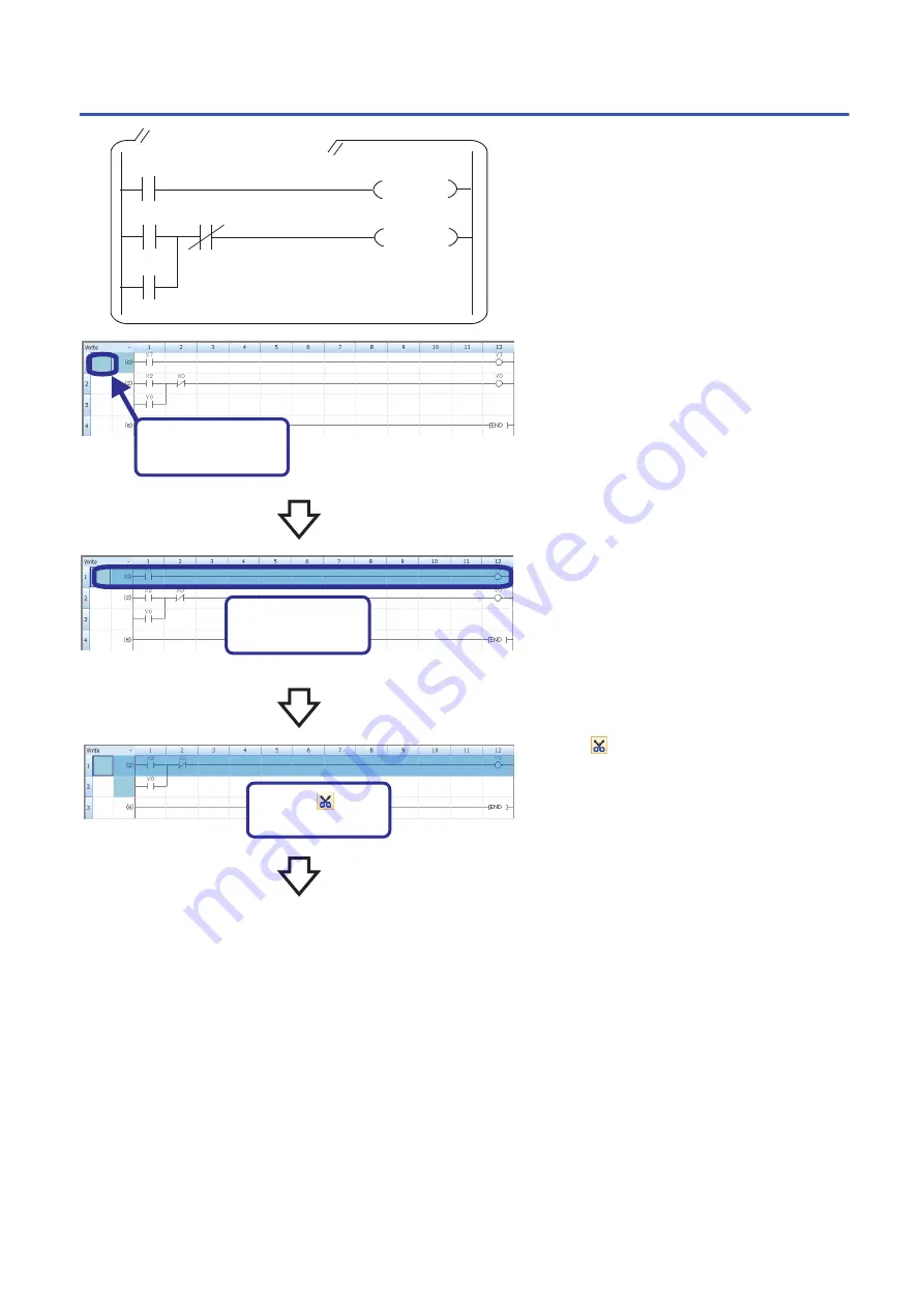
This section describes how to cut or copy a part of 
the ladder program shown on the left and paste the 
cut part or the copy of the part to any desired 
location in the ladder.

1.

Click and move the cursor to the position
where a part of the ladder program is to be cut.

2.

Drag the mouse to specify the cutting range.
The color of the specified range is highlighted.

To easily specify the range in units of ladder blocks, 
click the position where a step number is displayed 
and drag the mouse vertically.

3.

Click   on the toolbar, or select [Edit] → [Cut]
(

 + 

) to cut the ladder in the specified

range.

(To the next page)

X2

X100

Y0

Y0

A ladder program to be modified 

Y7

1.

Click and move

the cursor!

2.

Drag to specify

the range!

3.

Click       to cut

the range!

X7

41

Summary of Contents for FX5U Series

Page 1: ...FX5U Training Manual ...

Page 2: ...ld be activated Pushbutton switch Devices to detect the status of the system Selector switch Digital switch Digital indicator Devices to indicate the status of the system Devices to judge the status of the system and to provide instructions Pilot lamp PLC Input Solenoid valve Proximity switch Limit switch Actuator section Devices to drive the system Electromagnetic clutch Motor Output Control sect...

Page 3: ...er for industrial purposes A PLC incorporates an electrical circuit mainly comprised of a microcomputer and memory Input output interfaces exist between input output devices and the electronic circuit to connect them The programming panel is used to write a program to the memory in the PLC The term sequencer In Japan the term sequencer is widely used While Japan Electrical Manufacturer s Associati...

Page 4: ... coil of the input relay X1 is de energized and the N O contact of X1 is opened But the output relay Y0 is still energized since the N O contact is closed Self maintaining action When the input relay is energized by closing the limit switch LS1 the N C contact of X3 is opened then the coil of the output relay Y0 is de energized Reset As a result the pilot lamp PL distinguishes and the self maintai...

Page 5: ...ut relay is an inlet port on the PLC where an external signal provided from an input switch is received and indicated by the element symbol X The PLC incorporates an appropriate number of input relays Input terminal Data register D The data register is used as the storage box for storing the numerical data and it is indicated by the element symbol D Output contact of output relay single N O contac...

Page 6: ...ies from the start step of the program memory from left to right and from top to bottom in the order of 1 2 and 17 in units of a ladder block as shown below 1 X0 2 X1 5 X3 4 X2 6 X4 8 X5 9 X6 11 X7 13 X8 15 X9 16 XA 3 Y11 Y12 Y13 Y14 Y15 Y10 7 10 12 14 17 X10 X11 X12 6 ...

Page 7: ...t inserted or can be removed RD LED Lit when the CPU module is receiving data through built in RS 485 communication SD LED Lit when the CPU module is sending data through built in RS 485 communication SD RD LED Lit when the CPU module is sending or receiving data through built in Ethernet communication 7 Expansion board connector cover Cover for protecting expansion board connectors battery or oth...

Page 8: ...he RESET side for approximately 1 second 4 SD memory card disable switch Switch for disabling access to the SD memory card when the card is to be removed 5 Built in analog I O terminal block Terminal block for using the built in analog function 6 SD memory card slot Slot for inserting an SD memory card 7 Expansion board connector Connector for connecting an expansion board 8 Extension connector Co...

Page 9: ... points The output number Y connected to common is the range inside the thick separation line For transistor output source type the COM terminal is the V terminal X0 S S 0 V 24 V N L 1 2 3 4 5 6 7 X10 11 12 13 14 15 16 17 FX5U 32MR ES Input terminal Output terminal Partition Vacant terminal Do not use Output terminals connected to COM3 Y4 2 3 COM1 1 Y0 COM0 5 6 7 Y10 11 12 13 Y14 15 16 17 COM2 COM...

Page 10: ... 15 A Time lag fuse FX5U 64M E FX5U 80M E 250 V 5 A Time lag fuse Rush current FX5U 32M E 25 A max 5 ms or less 100 V AC 50 A max 5 ms or less 200 V AC FX5U 64M E FX5U 80M E 30 A max 5 ms or less 100 V AC 60 A max 5 ms or less 200 V AC Power consumption 1 FX5U 32M E 30 W FX5U 64M E 40 W FX5U 80M E 45 W 24 V DC service power supply capacity 2 FX5U 32M E 400 mA 300 mA 3 Supply capacity when service ...

Page 11: ...5U 32M X6 to X17 10 kHz FX5U 64M FX5U 80M X10 to X17 FX5U 64M FX5U 80M X20 and subsequent 0 1 0 05 kHz Pulse waveform Waveform T1 pulse width T2 rise fall time FX5U 32M X0 to X5 2 5 μs or more 1 25 μs or less FX5U 64M FX5U 80M X0 to X7 FX5U 32M X6 to X17 50 μs or more 25 μs or less FX5U 64M FX5U 80M X10 to X17 Input response time H W filter delay FX5U 32M X0 to X5 ON 2 5 μs or less OFF 2 5 μs or l...

Page 12: ...ls of the CPU module The service power supply or external power supply can be used for all inputs X of the CPU module However you need to select either one for each CPU module or I O module Both power supplies cannot be used together in the same module X0 S S 0V 24V FX5U 32MT ES N L X1 X0 S S X1 FX5 16EX ES 5V0V 24V Input terminal X0 S S X1 FX5 16EX ES 5V0V 24V 5V0V 24V Fuse 24 V DC Class D ground...

Page 13: ... CPU module The service power supply or external power supply can be used for all inputs X of the CPU module However you need to select either one for each CPU module or I O module Both power supplies cannot be used together in the same module X0 S S 0V 24V FX5U 32MT ESS N L X1 X0 S S X1 FX5 16EX ES 5V0V 24V Input terminal X0 S S X1 FX5 16EX ES 5V0V 24V 5V0V 24V Fuse Class D grounding 1 2 Three wi...

Page 14: ...put points common terminal 8 A or less 8 output points common terminal 8 A or less Min load 5 V DC 2 mA reference values Open circuit leakage current Response time OFF ON Approx 10 ms ON OFF Approx 10 ms Insulation of circuit Mechanical insulation Indication of output operation LED is lit when output is on Output circuit configuration A number is entered in the of COM AC power supply Load Fuse Y D...

Page 15: ...n Output circuit configuration Load Fuse DC power supply Y COM A number is entered in the of COM Load Fuse A number is entered in the of V Sink output wiring Source output wiring DC power supply Y V The transistor output type is a 4 point or 8 point common output type Sink output common Source output common Output to make load current flow into the output Y terminal is called sink output Output to...

Page 16: ...al output value Ambient temperature 25 5 Within 0 5 20 digit 2 Ambient temperature 0 to 55 Within 1 0 40 digit 2 Ambient temperature 20 to 0 1 Within 1 5 60 digit 2 Conversion speed 30 μs channels data refreshed every operation cycle Absolute maximum input 0 5 V 15 V Insulation method Inside the CPU module and the analog input circuit are not insulated Between input terminals channels is not insul...

Page 17: ...ls short circuit the V and V terminals Analog output wiring 1 For analog output wiring use shielded twisted pair cables double core type Separate them from other power lines or lines which can be induced by others 2 Ground a shielded cable at one point on the signal receiving side CH No goes in of V CH CH 33 k 82 7 k V V Shield 1 2 Class D grounding V V Class D grounding 2 Shield 1 Built in analog...

Page 18: ...and CPU module are directly connected a cross cable can be used Item Specifications Data transmission speed 100 10 Mbps Communication mode Full duplex FDX Half duplex HDX 1 Interface RJ45 connector Transmission method Base band Maximum segment length The distance between hub and node 100 m Cascade connection 100BASE TX Max 2 stages 2 10BASE T Max 4 stages 2 Protocol type CC Link IE field network B...

Page 19: ...ions Data transmission speed Max 115 2 kbps Communication method Full duplex FDX Half duplex HDX Maximum total extension distance 50 m Protocol type MELSOFT connection Non protocol communication MELSEC Communication protocol 3C 4C frames MODBUS RTU Predefined protocol support Inverter communication N N network Insulation method Not insulated Terminal resistors Built in OPEN 110 Ω 330 Ω Terminal bl...

Page 20: ...nding on the processing Setting parameters Users can set parameters for CPU modules I O modules and intelligent function modules GX Works3 manages programs and parameters in a project for each CPU module It has the following main functions Creating programs Ladder program ST program FBD LD program SFC program 20 ...

Page 21: ... values Writing data Reading data Programs can be monitored and debugged Pressing the buttons switches the ON OFF state of the contact Diagnostic function GX Works3 make diagnoses on the current error status and error history of the CPU module or network With the diagnostic function system recovery can be completed in a short time The system monitor shows detailed information on intelligent functi...

Page 22: ...on Click OK button when the next window appears Title bar Menu bar Toolbar A main screen used for operations such as programming parameter setting and monitoring Navigation window Connection Destination Cross Reference window Watch window etc Element Selection window Docked window Work window Status bar Screen Configuration Docking floating dockable windows Docked windows can be switched between t...

Page 23: ...stination on the menubar of the engineering tool 3 Click the Directy Connect to CPU button 4 Select Ethernet adapter the personal computer uses 5 Click the Connection Test button and check if the personal computer is connected to the CPU module 4 5 Initializing the CPU Module Online CPU Memory Operation 1 On the Memory Management window click the Initialization button 2 After the initialization pr...

Page 24: ...apacitor in the CPU module even though the power in the CPU module is turned OFF or the power failure exceeds the allowable momentary power failure time If an optional battery is used operation continues by the battery The clock data handled in the CPU unit is described below Data name Year Month Day Hour Minute Second Day of the week Description 4 digits in calendar year 1980 to 2079 1 to 12 1 to...

Page 25: ...il is to be input with the cursor and enter a device and label Users can switch a normally open contact and normally closed contact with the key If an added ladder is in contact with the right rail or is an output device Y DY the ladder is recognized as a coil If not it is recognized as a contact This section describes how to create a ladder program such as the one shown below Y0 X3 A ladder progr...

Page 26: ...ing the OK button also confirms the entry Clicking the Cancel button also cancels the entry 3 The added symbol is displayed 4 Move the cursor to the next position and enter X0 5 Press the key 6 The added symbol is displayed 7 Select the symbol and press the key to switch the symbol with To the next page 1 Enter the I O number 2 Press the Enter key 4 Enter the I O number 3 The symbol is displayed 5...

Page 27: ...ct Open Branch 12 Press the key 13 The added symbol is displayed 14 Move the cursor to the ladder under 15 Enter X3 16 Press the key To the next page 8 Enter the I O number 9 Press the Enter key 10 The symbol is displayed 11 12 Press the Enter key Enter Y0 and select Open Branch Y0 13 The symbol is displayed 14 Move the cursor 15 Enter the I O number 16 Press the Enter key Y0 Y0 27 ...

Page 28: ...The symbol is displayed 18 Enter the I O number 19 Press the Enter key X3 20 The symbol is displayed Y1 Converting the Program Compile the input ladder blocks 1 Select Convert Convert on the menu bar 2 When the conversion processing completes and the input ladder blocks are compiled the color of those ladder blocks changes from gray to white Saving the Project Save the created project Project Save...

Page 29: ...e Execute button 3 After the write processing completes click the Close button Resetting the CPU Module Reset the CPU module using the RUN STOP RESET switch located on the front of the CPU module Operate the RUN STOP RESET switch with your fingers Use of a tool such as a screwdriver may damage the switch Executing the Program Execute the program written to the programmable controller by using the ...

Page 30: ...rs Off On Flashing 4 Scan time details The scan time details are displayed Select the value to be displayed from the drop down list current value maximum value or minimum value 5 Monitor target selection Specify the monitor target FB instance when monitoring a FB program 1 2 3 4 5 Monitoring on the monitor status bar Monitoring on the ladder editor The on off states of contacts and coils and the c...

Page 31: ...pply may be shorted or overloaded Reconnect the modules and wire one by one to identify the cause Item to check Cause and action Check the installation of the battery Install the battery properly Check the battery voltage If the battery voltage is reduced replace the battery with a new one Battery voltage can be monitored with PLC data register SD8005 MELSEC iQ F FX5U User s Manual Hardware Item t...

Page 32: ...details can be checked Information required for troubleshooting such as the current error details and cause of the error and action to be taken are displayed The incorrect parameter setting and program error location can also be identified by selecting the error and clicking the Error Jump button On the Module Information List tab the LED status and the switch status of the target module can be ch...

Page 33: ...e it enables debugging without the connection with CPU module Debug Simulation Start Simulation Select the checkbox of the data to be written on the Online Data Operation screen and click the Execute button Select Debug Simulation Stop Simulation Starting a simulation GX Simulator3 is set as the connection destination during the simulation and Simulation system number of the simulator CPU number i...

Page 34: ...ottom right of the window When Insert is displayed press the key to switch to Overwrite When Insert is displayed contacts or coils are added 2 Click the position to be modified and press the F2 key To the next page A ladder program to be created Y0 Y0 X3 Y1 Y2 1 Check When changing X2 with X5 is attempted Added X5 X2 2 Press the F2 key X2 X0 3 The device can be modified Modify the device to Y2 and...

Page 35: ...e CPU module is in the RUN state Precautions Online change cannot be executed when the program in the CPU module and the program before the modification in GX Works3 do not match Thus when whether the programs match or not is unclear verify them before the modification with GX Works3 and execute the online change 1 Change the ladder 2 After the change click Convert Online Program Change from the m...

Page 36: ...con 2 Drag the icon from the position to the end position A vertical line is drawn on the left side of the cursor 3 Release the left button of the mouse to create a line To the next page A ladder program to be created Y0 Y0 X3 Y2 Y3 1 Click 2 Drag 3 A line is created X2 X0 4 Click on the toolbar and enter Y3 5 Click the OK button 5 Click 4 Click and enter the I O number 36 ...

Page 37: ...con 2 Drag the icon along the line to be deleted 3 Release the left button of the mouse to delete the line The line connected to END cannot be deleted 4 Press the key to delete 5 Click Convert Convert from the menu to convert the ladder program Y0 Y0 X3 Y2 Y3 1 Click 2 Drag 3 The line is deleted 4 Press the Delete key Y3 A ladder program to be created X2 X0 37 Lines can be added or deleted with th...

Page 38: ... move the cursor on the row desired position on the row where a new row is inserted above A new row is inserted above the row 2 Right click on the ladder editor and click Edit Insert Row from the menu To the next page 1 Click and move the cursor 2 Click X2 X0 Y0 Y0 X3 Y2 Y7 A ladder program to be modified X7 38 ...

Page 39: ... to confirm the entry 6 The added symbol is displayed 7 Click on the toolbar and enter Y7 8 Click the OK button 9 The added symbol is displayed 10 Click Convert Convert from the menu to convert the ladder program 3 A new row is inserted 4 5 Click Click and enter the I O number 7 8 Click Click and enter the I O number X7 9 The symbol is displayed Y7 39 ...

Page 40: ...ow desired position on the row to be deleted 2 Right click on the ladder editor and click Edit Delete Row from the right click menu 3 The row is deleted 4 Click Convert Convert from the menu to convert the ladder program X2 X0 Y0 Y0 X3 Y2 Y7 A ladder program to be modified 1 Click and move the cursor 2 Click 3 The row is deleted X7 40 ...

Page 41: ...m is to be cut 2 Drag the mouse to specify the cutting range The color of the specified range is highlighted To easily specify the range in units of ladder blocks click the position where a step number is displayed and drag the mouse vertically 3 Click on the toolbar or select Edit Cut to cut the ladder in the specified range To the next page X2 X100 Y0 Y0 A ladder program to be modified Y7 1 Clic...

Page 42: ...lick the position where a step number is displayed and drag the mouse vertically 6 Click on the toolbar or select Edit Copy 7 Click and move the cursor to a position on the ladder block any position on the block where the copy is to be pasted 8 Click on the toolbar or select Edit Paste from the menu 4 Click and move the cursor 5 Drag to specify the range 6 Click 7 Click and move the cursor The cop...

Page 43: ... check changes in a program 1 Click Online Verify with PLC from the menu 2 The Online Data Operation dialog box appears Select data to be verified 3 Click the Execute button 4 Verification results are displayed in the Result List window To check details of data double click the row of the data 1 Click 3 Click 2 Click and select 4 Double click 5 Detailed results are displayed 5 Displayed 43 ...

Page 44: ... when the input condition turns on and turns off the device when the condition turns off Timingchart Y0 X0 END X0 Y0 SET RST Setting resetting devices The SET instruction turns on a specified device when the input condition turns on and holds the on state of the device even though the condition turns off To turn off the device use the RST instruction Timingchart SET RST Y0 Y0 X1 X0 END X0 X1 Y0 44...

Page 45: ...0 Y0 X1 Operation will be the same Both of the following ladders hold the output END X0 Y0 Y0 X1 Using the SET instruction can hold the on status of the output even when the contact which drives the coil turns off Sequence When the input X0 is on and X1 is off the output Y0 turns on The output Y0 remains on even when the input X0 is turned off self holding Turning on the input X1 turns off the out...

Page 46: ...ge the output instruction OUT to OUTH to select a high speed retentive timer OUT ST1 K50 The operation of the timer contact delays by a set time after the coil is energized On delay timer The setting range of a timer value is K1 to K32767 Low speed 100ms timer 0 1 to 3276 7 seconds High speed 10ms timer 0 01 to 327 67 seconds When the value set to a timer is 0 it is turned on timeout by the execut...

Page 47: ...relay about system clock is shown below No Name Description SM400 Always ON SM401 Always OFF SM402 After RUN ON for one scan only SM403 After RUN OFF for one scan only SM409 0 01 second clock SM410 0 1 second clock SM411 0 2 second clock SM412 1 second clock SM413 2 second clock ON OFF ON OFF ON OFF 1 scan ON OFF 1 scan 0 005 s 0 005 s 0 05 s 0 05 s 0 1 s 0 1 s 0 5 s 0 5 s 1 s 1 s 47 ...

Page 48: ... rising edges of the subsequent input signals Once counting is up the contact status and the current value count value of the counter do not change until the RST instruction is executed Executing the RST instruction before counting is up clears the counter value to 0 The setting range of a counter value is K0 and K32767 K0 turns on starts counting at execution of the instruction Contact X1 Coil C2...

Page 49: ...f one scan This section describes the operation timing of the PLS PLF instruction 1 The PLS instruction turns on a specified device only for one scan at the rising edge of the commanded condition Timing chart 2 The PLF instruction turns on a specified device only for one scan at the falling edge of the commanded condition Timing chart X0 X1 M5 PLS PLF M0 1 2 END X0 M5 One scan One scan X1 M0 One s...

Page 50: ...X0 Y0 X2 Y0 Y0 X0 If the rising edge pulse contact and the falling edge pulse contact are used the operation of the previously described PLS PLF instruction can be written more simply They can be used according to the content and function of the following programs When the PLS instruction is used When the rising edge pulse contact instruction is used X2 0 M0 Y0 3 X0 PLS M0 Y0 0 Y0 X0 X2 Y0 Useful ...

Page 51: ...utton switch is pressed Timing chart X0 Y0 Y0 M0 Y0 M0 PLS X0 M0 Y0 E ND X1 Y1 FF In an on off repeat ladder Y1 turns on when X1 turns on for the first time and turns off when X1 turns on again Timing chart X1 Y1 Useful application of the PLS PLF instructions Part 3 These instructions can be used in a program that executes an output operation for a set period of time at timing when an input signal...

Page 52: ...d start Operation memory 2 Operation memory 1 Next process PLF Proceed to the next process Process JOB 1 program M101 Sequence memory M102 Start PLS M111 Completed PLS 1 M110 Operation memory 1 M110 Operation memory 1 M110 Operation memory 1 X1 Completion condition 1 PLS M111 Completed PLS 1 M110 Operation memory 1 PLF M112 Next process PLF 1 Process JOB 2 program M101 Sequence memory M112 Next pr...

Page 53: ...yor rightward operation RY1 RY2 Ladder example 1 The following program runs automatic operations After X0 is turned on the system operates in the low speed mode for 3sec Then the system operates in the high speed mode for 10sec and stops Low speed High speed 3sec 10sec X0 T1 M110 M110 OUT T1 K30 M110 PLF M112 M112 T2 M120 M120 OUT T2 K100 M110 Y1 M120 Y2 Instruction for auto low speed Instruction ...

Page 54: ... X0 is turned on the system operates in the low speed mode for 3sec Then the system operates in the high speed mode for 10sec and stops Low speed High speed 3sec 10sec X7 M100 X7 M101 M100 X2 M82 M81 X3 M81 M82 M101 X0 T1 M110 M110 OUT T1 K30 M110 PLF M112 M101 M112 T2 M120 M120 OUT T2 K100 M81 Y1 M110 M82 Y2 M120 Automatic start Instruction for auto low speed Instruction for auto high speed Low s...

Page 55: ...s according to ladder When the execution command of MC instruction turns OFF the operation result between the MC and MCR instructions becomes as follows Device Device status Timer The count value becomes 0 and both coils and contacts turn OFF Counters retentive timers Coils turn OFF but the current status of both count values and contacts is maintained Devices in OUT instruction Forcibly turned OF...

Page 56: ...s the system to the high speed operation mode When the automatic operation is selected by turning on X7 After X0 is turned on the system operates in the low speed mode for 3sec Then the system operates in the high speed mode for 10sec and stops X7 MC N0 M100 N0 M100 X2 M82 M81 X3 M81 M82 MCR N0 X7 MC N0 M101 N0 M101 X0 T1 M110 M110 OUT T1 K30 M110 PLF M112 M112 T2 M120 M120 OUT T2 K100 MCR N0 M81 ...

Page 57: ... left The following shows how a decimal value in this case 153 is represented Power of digit can be expressed as follows n Digit number 0 1 2 10 Decimal value In the programmable controller the symbol K is used to represent a value in decimal 153 100 50 3 1 100 5 10 3 1 1 102 5 101 3 100 Decimal symbol 0 to 9 Power of digit Binary BIN A binary value consists of two symbols 0 and 1 which represent ...

Page 58: ...ue in hexadecimal Hexadecimal values are used to represent the following device numbers Link relay B Link register W Link special relay SB Link special register SW Decimal Binary 0 0 0000 1 1 0001 2 2 0010 3 3 0011 4 4 0100 5 5 0101 6 6 0110 7 7 0111 8 8 1000 9 9 1001 10 A 1010 11 B 1011 12 C 1100 13 D 1101 14 E 1110 15 F 1111 16 10 10000 17 11 10001 18 12 10010 1 9 1 0 1 4 A 9 D 1 0 1 0 1 0 0 1 1...

Page 59: ... 1 1 0 1 0 0 0 1 1 0 0 1 Numerical values used by the programmable controller Usually 8 bits are called one byte and 16 bits two bytes are called one word Registers of each word device in the programmable controller consist of 16 bits Data register D Current value of a timer T Current value of a counter C File register R Link register W Values in the following two ranges can be processed in 16 bit...

Page 60: ...00 00001101 00000000 00001110 00000000 00001111 10 11 12 13 14 15 000A 000B 000C 000D 000E 000F 00000000 00010110 00000000 00010111 00000000 00011000 00000000 00011001 00000000 00100000 00000000 00100001 00000000 00100010 00000000 00100011 00000001 00000000 00000001 00100111 00000010 01010101 00010000 00000000 00100000 01000111 01000000 10010101 00000000 00010000 00000000 00010001 00000000 0001001...

Page 61: ... the same way As long as the device numbers of four bit device areas are in consecutive order any bit device can be specified as the start device M 19 M 18 M 17 M 16 M 15 M 14 M 13 M 12 M 11 M 10 M 9 M 8 M 7 M 6 M 5 M 4 M 3 M 2 M 1 M 0 Internal relay M K1M0 K2M6 K3M5 Bit Specification of a Word Device D b By specifying a bit of a word device the specified bit can be used as bit data When specifyin...

Page 62: ...ue transferred to the data register D102 and stored there in binary T0 T0 X1 C10 RST X2 D100 T0 MOV X3 D101 C10 MOVP X4 D102 K157 MOVP X5 D103 H4A9D MOVP X7 K50 T0 OUT K1500 C10 OUT s d T0 128 D100 128 45 64 32 16 1 2 4 8 64 32 16 1 2 4 8 1 1 1 1 0 0 0 0 0 0 0 0 0 0 0 0 1 1 1 1 0 0 0 0 0 0 0 0 0 0 0 0 0 0 0 D102 128 K157 1 8 2 16 4 32 64 1 0 0 0 0 0 0 0 1 1 1 1 0 When the input condition turns on ...

Page 63: ...uted only once Data is transferred only in one scan after the input condition turns on Data is transferred only once Data is transferred at every scan while the input condition is on X4 D102 K157 MOVP X4 M1 PLS M1 D102 K157 MOV Same Items to be checked Inputs X2 X3 X4 X5 and X7 On Monitor the values in the data register D100 to D103 After writing data to the programmable controller click Online Mo...

Page 64: ...2048 16384 4 A 9 D Hexadecimal H4A9D 19101 Word devices are expressed with the on off states of bits Off 0 in binary On 1 in binary Current values of a timer and counter are monitored The values change This value indicates that a decimal number 157 K157 has been stored This value indicates the decimal number of the hexadecimal number 4A9D Binary bit weight Sign bit 0 0 1 0 64 ...

Page 65: ... the hexadecimal notation Select HEX for Value in the Device Format dialog box Device Buffer Memory Batch Monitor window Change the display of the numerical values being monitored in a multi point format Select Word Multi point for Display Unit Format in the Device Format dialog box Device Buffer Memory Batch Monitor window Value in D103 Value in D102 Value in D101 Value in D100 65 ...

Page 66: ...5 365 365 365 D100 D101 D102 D107 d s n 8 sets of data K8 Same X6 K8 D100 K0 FMOV X6 D100 RST D101 RST D107 RST BMOV When the input condition turns on the BMOV instruction batch transfers the n points of data stored starting from the device specified by s to the areas starting from the device specified by d The following figure shows the operation of when X5 turns on and the BMOV instruction is ex...

Page 67: ...1 1 1 0 0 0 0 0 0 0 0 1 1 1 1 1 1 1 1 1 1 1 1 1 1 0 0 0 0 0 0 0 0 s d 103 102 101 100 1 BCD 1 Set 0s Data specified by s can be converted if it is within the range from K0 to K9999 BCD decimal The table below shows nibble specification for the data in the device specified by s and d Precautions Binary data is used in all operations in CPU module including arithmetic operations increment and decrem...

Page 68: ...0 800 400 200 100 80 40 20 10 8 4 2 1 1 1 0 0 0 0 0 0 0 0 1 1 1 1 1 1 1 1 1 1 1 1 1 1 0 0 0 0 0 0 0 0 s d 103 102 101 100 1 BIN The data in the device specified by s can be converted if it is in the range from 0 to 9999 BCD The table below shows nibble specification for the data in the device specified by s and d Precautions Binary data is used in all operations in CPU module including arithmetic ...

Page 69: ...nuity state when the value in the source 1 is smaller than that in the source 2 The ladder goes in the continuity state when the value in the source 1 is larger than that in the source 2 The ladder goes in the continuity state when the value in the source 1 is equal to or smaller than that in the source 2 The ladder goes in the continuity state when the value in the source 1 is equal to or larger ...

Page 70: ...n the value in the device specified in s1 is added to the value in the device specified in s2 and the result is stored in the device specified in d Precautions Always use or as the addition or subtraction instructions When or is used an addition or subtraction operation is executed at every scan To use or convert operands into pulse in advance X2 D100 K5 P X3 D101 K100 D100 P 1 2 END s1 s d d s2 d...

Page 71: ...the value in the device specified in S2 is subtracted from the value in the device specified in S1 and the result is stored in the device specified in d K1 D100 P D102 K1 P Addition Subtraction INCP D100 DECP D102 X4 D102 K1000 MOVP X5 d s2 X6 D103 K50 D102 P d s1 D102 K10 s 3 4 END P D102 10 D102 Input condition First ON Second ON Third ON 1000 example 990 980 10 10 10 990 980 970 The value in D1...

Page 72: ...a a space of 16 bits 1 word is not enough Thus the D110 specified in the program and the subsequent device area D111 are used for storing the result D110 s1 d s2 2 When the input condition turns on the value in the device specified in s1 is divided by the value in the device specified in s2 and the result is stored in the device specified in d Values after the decimal point of the division result ...

Page 73: ...tor and click Online Watch Register to Watch Window Watch Window 1 2 D20 is registered in the Watch 1 window 3 Right click D20 in the Watch 1 window and click Start Watching 4 Watching of Watch 1 starts 5 Enter 4000 in Current Value 1 Click 3 Click 5 Enter The current values of word devices can also be registered started watching and changed in the watch window with selection the cell on the ladde...

Page 74: ...ignificant bit b31 b15 for 16 bit data is processed as a sign bit Instruction Transfer MOV P DMOV P Comparison D D D D D D Arithmetic operation P D P P D P P D P P D P Available range of numerical values 32768 to 32767 2147483648 to 2147483647 Available range of digit specification K1 to K4 K1 to K8 1 word 16 bits 32 bits 2 words 1073741824 2147483648 536870912 268435456 134217728 67108864 3355443...

Page 75: ...result is stored in two adjacent device areas D110 D101 D100 D111 D110 D101 D100 D0 D110 DMOV D111 D110 MOV s1 s2 d D140 D130 D120 D D131 D130 D0 D140 DMOV D121 D120 Quotient D141 D140 Remainder D143 D142 Quotient display D10 D142 DMOV Remainder display When the value is outside the range of 0 to 32767 it cannot be properly displayed Set 32 bit Integer Signed for Data Display Format Click the OK b...

Page 76: ...ecimal constant or indirectly specified with D data register In the program shown below the setting value can be changed from an external device X4 SM400 X1 D106 D21 MOVP X6 C10 RST X0 D105 D20 MOVP T10 Y0 D0 T10 MOV X5 C10 Y1 SM400 D1 C10 MOV Initial input device D105 1 2 3 4 D0 displays the current value of T10 D105 T10 OUT D106 C10 OUT D20 1 2 3 4 Initial input device D106 1 2 3 4 D1 displays t...

Page 77: ... 3 Press the key 4 Click each of comment areas and enter comments as shown on the left 5 Click Device Name and enter Y0 in the list box 6 Press the key 7 Click a comment area and enter a comment as shown on the left 1 Double click 4 Enter comments 2 Enter 7 Enter a comment 5 Enter 77 This section describes how to create comments device comments statements and notes in a program Creating comments ...

Page 78: ...ng a ladder with comments in windows of GX Works3 Click View Comment Display from the menu Statments and notes As well as device comments statements and notes can be created in a ladder Statement A comment that describes the function or application of a ladder block Note A comment that describes the function or application of an output or instruction Statements and notes are classified into two ca...

Page 79: ...ding ladder blocks can be displayed After entering statements is completed select Edit Documentation Edit Statement again Creating statments Precautions When copying or deleting a line statement displayed in the Navigation window the ladder blocks between the selected line statement and the next statement are copied or deleted Select Edit Documentation Edit Note and double click an output or instr...

Page 80: ...izontal downward or double click it In another way use the following menu Select Window Split Drag the splitter bar vertical to the left or double click it Since split ladder editors can be scrolled separately programs which are described in different parts can be displayed at once Horizontal sprit Vertical sprit 80 ...

Reviews: