27
5
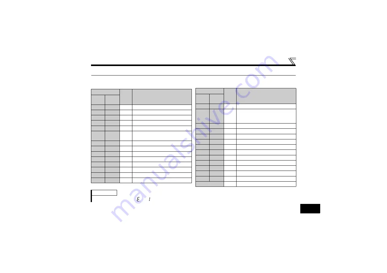
5.4 Output Signal List
For details of signal definitions, refer to
Pr. 190 to Pr. 192 (Output terminal function selection) of the inverter
instruction manual
.
Setting
Signal
Name
Function
Positive
Logic
Negative
Logic
0
100
RUN Inverter running
1
101
SU
Up to frequency
3
103
OL
Overload warning
4
104
FU
Output frequency detection
7
107
RBP Regenerative brake pre-alarm
8
108
THP
Electronic thermal O/L relay pre-
alarm
11
111
RY
Inverter operation ready
12
112
Y12 Output current detection
13
113
Y13 Zero current detection
14
114
FDN PID lower limit
15
115
FUP PID upper limit
16
116
RL
PID forward/reverse rotation output
20
120
BOF Brake opening request
25
125
FAN Fan fault output
26
126
FIN Heatsink overheat pre-alarm
46
146
Y46
During deceleration at occurrence
of power failure (retained until
release)
47
147
PID During PID control activated
64
164
Y64 During retry
80
180
SAFE Safety monitor output
81
181
SAFE2 Safety monitor output 2
90
190
Y90 Life alarm
91
191
Y91 Fault output 3 (Power-off signal)
93
193
Y93 Current average monitor signal
95
195
Y95 Maintenance timer signal
96
196
REM Remote output
98
198
LF
Alarm output
99
199
ALM Fault output
9999
⎯
No function
Setting
Signal
Name
Function
Positive
Logic
Negative
Logic
REMARKS
• When an option fault (
) occurs, all outputs are tuned off.


