


22
FTC4 Installation Manual
16
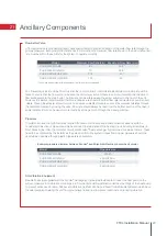
Controller Options
The FTC4 (cased) comes factory fitted with a main controller. This incorporates a thermistor for temperature
monitoring and a graphical user interface to enable set-up, view current status and input scheduling functions. The
main controller is also used for servicing purposes. This facility is accessed via password protected service menus.
To provide the best efficiency Mitsubishi Electric recommends using room compensation function. To use this
function a room thermistor needs to be present in a main living area. This can be done in a number of ways the
most convenient are detailed below.
Refer to controller section of this manual for instructions on how to set compensation curve, flow temp, room
compensation or thermistor input.
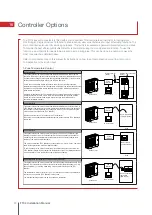
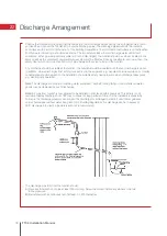
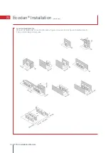
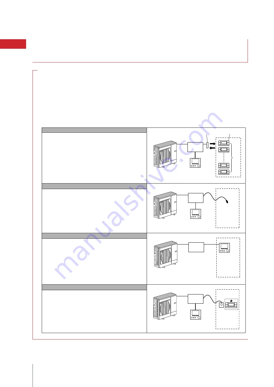
1-Zone Temperature Control
Control option A
This option features the main controller and the Mitsubishi Electric wireless remote
controller. The wireless remote controller is used to monitor room temperature and can
be used to make changes to the space heating settings, boost DHW (*1) and switch to
holiday mode without having to directly use the main controller.
If more than one wireless remote controller is used, the most recently requested
temperature setting will commonly be applied to all rooms by the central control system
regardless of which wireless remote controller was used. No hierarchy exists across
these remote controllers.
Wire the wireless receiver to FTC-4 (Master) referring to the wireless remote controller
instruction manual.
Turn DIP SW1-8 to ON.
remote controller to transmit and receive data referring to the wireless remote
controller installation manual.)
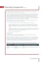
Control option B
This option features the main controller and the Mitsubishi Electric thermistor wired to
FTC-4 (Master). The thermistor is used to monitor room temperature but can not make
any changes in control operation. Any changes to DHW (*1) must be made using the
main controller mounted on the FTC-4 (Master).
Wire the thermistor to the TH1 connector on FTC-4 (Master).
The number of room temperature thermistors that can be connected to FTC-4 (Master) is
always one.
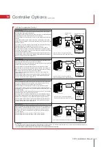
Control option C
This option features the main controller being removed from the FTC-4 (Master) and situ-
ated in a different room. A thermistor built in the main controller can be used for monitor-
ing the room temperature for Auto Adaptation function whilst keeping all its features of
the main controller available.
The main controller and FTC-4 (Master) are connected by a 2-core, 0.3 mm², non-polar
To use the sensor in the main controller the main controller should come off from the
FTC-4 (Master). Otherwise it will detect the temperature of the FTC-4 (Master) instead of
room temperature. This will affect the output of the space heating.
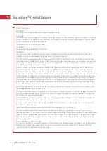
Control option D (Flow temp. or compensation curve only)
This option features the main controller and a locally supplied thermostat wired to FTC-4
(Master). The thermostat is used to set the maximum temperature for heating room. Any
changes to DHW (*1) must be made using main controller mounted on the FTC-4
(Master).
The thermostat is wired to IN1 in TBI.1 on FTC-4 (Master). The number of thermostats
that can be connected to FTC-4 (Master) is always one.
The wireless remote controller can be also used as a thermostat.
Outdoor unit
Outdoor unit
Outdoor unit
Outdoor unit
Wireless receiver
(option)
Main controller
Wireless remote controller
(option)
Main controller
Main controller
Main controller
(remote position)
Max. 8
Room
Room
Room temperature
thermistor (option)
Room
Room temperature
thermostat
FTC-4
(Master)
FTC-4
(Master)
20.0°C
FTC-4
(Master)
20.0°C
20.0°C
20.0°C
20.0°C
FTC-4
(Master)
This option features the main controller and the Mitsubishi Electric thermistor wired to
FTC4 (Master). The thermistor is used to monitor room temperature but can not make
any changes in control operation. Any changes to DHW (*1) must be made using the
main controller mounted on the FTC4 (Master).
Wire the thermistor to the TH1 connector on FTC4 (Master).
The number of room temperature thermistors that can be connected to FTC4 (Master) is
always one.
This option features the main controller being removed from the FTC4 (Master) and
situated in a different room. A thermistor built in the main controller can be used for
monitoring the room temperature for Auto Adaptation function whilst keeping all its
features of the main controller available.
The main controller and FTC4 (Master) are connected by a 2-core, 0.3 mm², non-polar
cable (field supply) with a maximum length of 500m.
To use the sensor in the main controller the main controller should come off from the
FTC4 (Master). Otherwise it will detect the temperature of the FTC4 (Master) instead of
room temperature. This will affect the output of the space heating.
This option features the main controller and a locally supplied thermostat wired to FTC4
(Master). The thermostat is used to set the maximum temperature for heating room. Any
changes to DHW (*1) must be made using main controller mounted on the FTC4
(Master).
The thermostat is wired to IN1 in TBI.1 on FTC4 (Master). The number of thermostats
that can be connected to FTC4 (Master) is always one.
The wireless remote controller can be also used as a thermostat.
This option features the main controller and the Mitsubishi Electric wireless remote
controller. The wireless remote controller is used to monitor room temperature and can
be used to make changes to the space heating settings, boost DHW (*1) and switch to
holiday mode without having to directly use the main controller.
If more than one wireless remote controller is used, the most recently requested
temperature setting will commonly be applied to all rooms by the central control system
regardless of which wireless remote controller was used. No hierarchy exists across
these remote controllers.
Wire the wireless receiver to FTC4 (Master) referring to the wireless remote controller
instruction manual. Turn DIP SW1-8 to ON. Before operation configure the wireless
remote controller to transmit and receive data referring to the wireless remote
controller installation manual.)
FTC4
(Master)
FTC4
(Master)
FTC4
(Master)
FTC4
(Master)
Summary of Contents for Ecodan HUS210FTC4ST
Page 2: ......
Page 8: ...5 Pipework Configuration 8 FTC4 Installation Manual ...
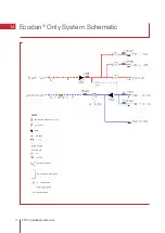
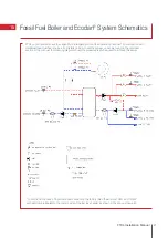
Page 20: ...20 FTC4 Installation Manual 14 Ecodan Only System Schematic ...
Page 83: ......


