
24
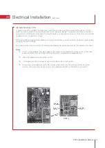
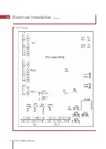
Electrical Installation
(continued)
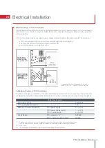
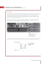
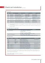
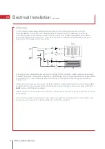
Signal Inputs
*1.
If using outdoor thermostat for controlling operation of heaters, the lifetime of the heaters and related parts
may be reduced.
*2.
To turn on the boiler operation, use the main controller to select ‘Boiler’ in ‘External input setting’ screen in
the service menu.
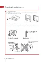
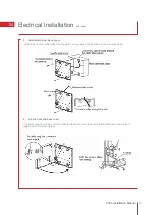
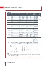
Wiring Specification for Signal Inputs
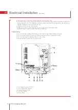
Thermistor Inputs
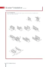
Do not splice the wiring to extend or shorten it as this could affect correct monitoring of each temperature. If the
wiring is too long, bundle it with a strap to adjust the length. When the wires are wired to adjacent terminals, use
ring terminals and insulate the wires.
*1.
The maximum length of the thermistor wiring is 5m.
*2.
Except PAC-IF052B
47
FTC4 Installation Manual
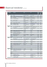
IN1
TBI.1 1-2
Room thermostat 1 input
Refer to SW2-1
Refer to SW2-1
IN2
TBI.1 3-4
Flow switch 1 input
Refer to SW2-2
Refer to SW2-2
IN3
TBI.1 5-6
Flow switch 2 input (Zone 1)
Refer to SW3-2
Refer to SW3-2
IN4
TBI.1 7-8
Demand control input
Normal
Heat source OFF/Boiler
operation *
2
IN5
TBI.1 9-10
Outdoor thermostat input (*
1
)
Standard operation
Heater operation/Boiler
operation *
2
IN6
TBI.1 11-12
Room thermostat 2 input
Refer to SW3-1
Refer to SW3-1
IN7
TBI.1 13-14
Flow switch 3 input (Zone 2)
Refer to SW3-3
Refer to SW3-3
Name
Terminal
Function
OFF (Open)
ON (Short)
TH1
-
CN20
Thermistor (Room temp) *
1
PAC-SE41TS-E
TH2
-
CN21
Thermistor (Ref liquid temp) *
2
-
THW1
-
CNW12 1-2
Thermistor (Flow water temp)
-
THW2
-
CNW12 3-4
Thermistor (Return water temp)
-
THW5
-
CNW5
Thermistor (DHW tank water temp) *
1
PAC-TH011TK-E
THW6
TBI.2 7-8
-
Thermistor (Zone1 flow water temp) *
1
PAC-TH011-E
THW7
TBI.2 9-10
-
Thermistor (Zone1 return water temp)*
1
THW8
TBI.2 1-2
-
Thermistor (Zone2 flow water temp) *
1
PAC-TH011-E
THW9
TBI.2 11-12
-
Thermistor (Zone2 return water temp)*
1
THWB1 TBI.2 3-4
-
Thermistor (Boiler flow water temp)*
1
PAC-TH011HT-E
Name
Terminal
Connector
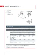
Item
Optional Part
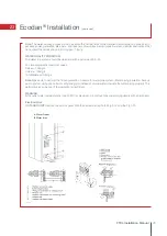
Signal input wire
Use sheathed vinyl coated cable
Maximum 10m
Wire type: CV, CVS or equivalent
Wire size: Stranded wire 0.5mm
2
to 1.25mm
2
Switch (or Thermostat)
Non voltage ‘a’ contact signals
Remote switch: Minimum applicable load 12V DC, 1mA
Name
ON (Short)
Summary of Contents for Ecodan HUS210FTC4ST
Page 2: ......
Page 8: ...5 Pipework Configuration 8 FTC4 Installation Manual ...
Page 20: ...20 FTC4 Installation Manual 14 Ecodan Only System Schematic ...
Page 83: ......


