5
9.2
Pipe work
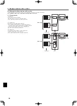
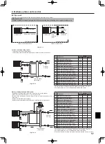
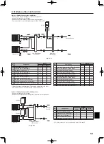
Following is the system example of two outdoor units being connected in one system.
IMPORTANT NOTE
Keep the minimum amount of water required in the space heating circuit according to the number of outdoor units.
No. Component
Wiring
Master Slave 1 Slave 2
1
Booster heater (field supply)
2
Circulation pump1 (field supply)
3
Flow switch1 (field supply) *2
4
Flow temp. thermistor (THW1)
5
Return temp. thermistor (THW2)
6
Slave1 circulation pump1 (field supply)
7
Slave1 flow switch (field supply) *2
8
Slave1 flow temp. thermistor (THW1)
9
Slave1 return temp. thermistor (THW2)
10 Slave1 ref. liquid temp. thermistor (TH2) *1
11
Slave2 circulation pump1 (field supply)
12
Slave2 flow switch (field supply) *2
13
Slave2 flow temp. thermistor (THW1)
14 Slave2 return temp. hermistor (THW2)
15 Slave2 ref. liquid temp. thermistor (TH2) *1
System 1: Heating/Cooling system
• Install a low loss header (field supply).
• Install booster heater toward the local system, relative to the low loss header.
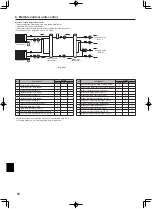
System 2: Heating/Cooling & DHW system
• Install DHW tank toward the outdoor unit , relative to the low loss header.
• Wire 3-way valve (or 2-way valve 1, 2 to FTC (slave unit).
• LP mode uses assistance of electric heater. Place an immersion heater on the
DHW circuit.
• Install a low loss header (field supply).
• Install booster heater toward the local system, relative to the low loss header.
*1 When the outdoor unit is split type, TH2 needs to be installed. <Fig. 9.2.1>
*2 For safety protection, it is recommended to install a flow switch.
No. Component
Wiring
Master Slave 1 Slave 2
1
Booster heater (field supply)
2
Circulation pump1 (field supply)
3
Flow switch1 (field supply) *2
4
Immersion heater (field supply)
5
Flow temp. thermistor (THW1)
6
Return temp. thermistor (THW2)
7
Tank water temp. (THW5)
8
Slave1 circulation pump1 (field supply)
9
Slave1 flow switch (field supply) *2
10
Slave1 3-way valve (field supply) *3
11
Slave1 flow temp. thermistor (THW1)
12 Slave1 return temp. thermistor (THW2)
13 Slave1 ref. liquid temp. thermistor (TH2) *1
14
Slave2 circulation pump1 (field supply)
15
Slave2 flow switch (field supply) *2
16
Slave2 flow temp. thermistor (THW1)
17 Slave2 return temp. thermistor (THW2)
18 Slave2 ref. liquid temp. thermistor (TH2) *1
*1 When the outdoor unit is split type, TH2 needs to be installed. <Fig. 9.2.1>
*2 For safety protection, it is recommended to instal a flow switch.
*3 The use of two 2-way valves can perform the same function as a 3-way valve.
4
8
9
5
6
2
1
7
13
15
14
11
12
3
10
. Multiple outdoor units control
Outdoor unit
Outdoor unit
Flow temp. thermistor
Return temp. thermistor
Flow temp.
thermistor
Return temp.
thermistor
Outdoor unit (Packaged type)
Outdoor unit (Split type)
Low loss header
(field supply)
Heating/
Cooling
7
4
5
10
1
6
2
3
11
12
8
9
16
17
14
15
13
18
Outdoor unit
Outdoor unit
Low loss header
(field supply)
DHW tank
Heating/
Cooling
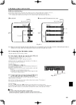
<Fig. .2.1>
<Fig. .2.2>
<Fig. .2.3>
Ref. liquid
temp.
thermistor
(TH2)
*1
*1 Refrigerant-water HEX
*1 Refrigerant-water HEX
*1

