background image

•••••••••••••••••••••••••••••••••••••••••••••••••••••••••••••••••••••••••••••••••••••••••••••••••••••••••••••••••••••••••••••••••••••••••••••••••••

12

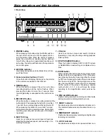
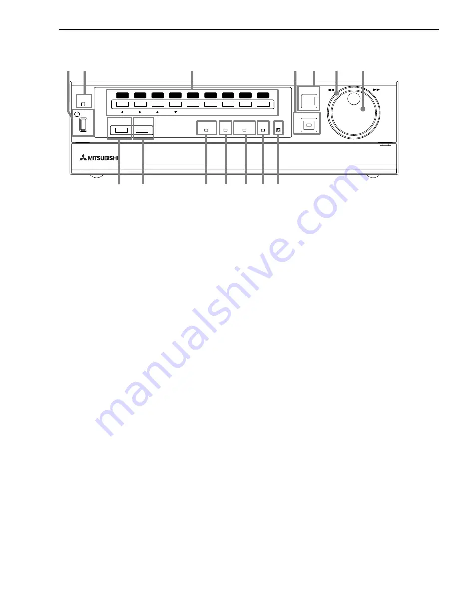
1. POWER button

When pressing this button while the MAIN switch on
the rear of this unit is set to ON, the power turns on
and the button lights. When the button is pressed
again, the unit will be in standby and the light will
turn off. When the unit is in operational transition such
as booting, the button will flash and other operations
are not accepted.

2. ACCESS indicator

Illuminates during access to hard disk drive or Com-
pact Flash Card.

3. Camera number buttons (1 to 9)

Press the button to display the image on the monitor
of the camera connected to that channel.

4. TIMER button

When this button is pressed the unit is set to timer
recording/standby and the button flashes. When
pressing this button for more than 1 second, timer
recording/standby is cancelled and the button turns
off.

5. REC/STOP button

When this button is pressed, recording starts and the
button lights. When pressing the button for more than
1 second, the recording stops and the light turns off.
When pressing this button for more than 1 second
during alarm recording, recording stops. During timer
recording, recording will not stop even if the button
is pressed.

6. SHUTTLE ring

Used to set various menus and search functions,
adjusting the playback speed, and reversing or for-
warding the image.

7. JOG dial

Used to set various menus and search functions,
forwarding or reversing the image during playback
(field-by-field).

8. SPLIT/SEQUENCE button

Press the button to display SPLIT4 ,SPLIT9 screen
or SEQUENCE screen setting on multiplexer func-
tions.

9. ZOOM button

When pressing this button once during single screen
display, the screen is magnified by 100%. In the same
way, pressing the button twice magnifies the screen
by 200% and pressing the button three times magni-
fies the screen by 400%. During single screen dis-
play, the magnification center point (X) is displayed
on the center of the screen. Pressing a camera
number button (1, 2, 3, or 4) will move the screen
according to the magnification center point as the
axis.

10. PRE ALARM indicator

Flashes during pre-alarm recording and illuminates
during pre-alarm recording stand-by mode.

11. M-DET indicator

Illuminates when the motion detection function is on.
The indicator flashes when motion detection is in op-
eration.

12. EMERGENCY indicator

Flashes during emergency recording and lights when
recording is completed.

13. LOCK indicator

Illuminates when simple lock or password lock is on.

Major operations and their functions

■ 

Front View

TIMER

ENTER/

FF

CLEAR/

REW

M-DET

PRE ALARM

LOCK

EMERGENCY

SPLIT/

SEQUENCE

ZOOM

ACCESS

REC/STOP

DIGITAL RECORDER DX-TL900U

POWER

5

6

7

8

9

1

2

3

4

10

14

13

12

11

8

9

7

6

5

1

2

3

4

Summary of Contents for DX-TL900U

Page 1: ...1 DIGITAL RECORDER INSTALLATION AND OPERATION MANUAL MODEL DX TL900U THIS INSTRUCTION MANUAL IS IMPORTANT TO YOU PLEASE READ IT BEFORE USING YOUR DIGITAL RECORDER ...

Page 2: ... PARTS INSIDE REFER SERVICING TO QUALIFIED SERVICE PERSONNEL RISK OF ELECTRIC SHOCK DO NOT OPEN WARNING The lightning flash with arrowhead symbol within an equilateral triangle is intended to alert the user to the presence of uninsulated dangerous voltage within the product s enclosure that may be of sufficient magnitude to constitute a risk of electric shock The exclamation point within an equila...

Page 3: ...t qui peuvent être suffisamment importantes pour conduire au risque d électrocution Le point d exclamation au sein d un triangle équilateral a pour objet de tirer l attention de l utilisateur sur le fait qu il y a des instructions de mise en service et d entretien de réparation dans les fiches descriptives de l appareil qui doivent obligatoirement être respectées AVERTISSEMENT AFIN D ÉVITER TOUT R...

Page 4: ...to ensure reliable operation of the product and to protect it from overheating and these openings must not be blocked or covered This prod uct should never be placed near or over a radiator or heat register This product should not be placed in a built in installation such as a bookcase or rack un less proper ventilation is provided or the manufac turer s instructions have been adhered to 10 Power ...

Page 5: ...tics as the original part Unauthorized sub stitutions may result in fire electric shock or other hazards 19 Safety Check Upon completion of any service or repairs to this product ask the service technician to perform safety checks to determine that the product is in safe oper ating conditions 20 Heat The product should be situated away from heat sources such as radiators heat registers stoves or o...

Page 6: ...d the unit and place the unit on a hard level surface only and ensure it is not covered during use Heavy objects should never be placed on the unit WHEN NOT IN USE When not in use always turn OFF the MAIN switch CABINET CARE Never use petroleum based cleaners Clean with a soft cloth moistened with soap and water and wipe dry PVC cables or leads should not be left in contact with the cabinet surfac...

Page 7: ...formed in maximum intervals and maximum picture quality using the camera specified for alarm recording or nor mal recording Title comment recording function This unit can record characters inputted from a PC with RS 232C connection as comments along with the video audio When setting the display title the title can also be recorded along with the video Dis play is also possible using another unit C...

Page 8: ...32 The function of the SPLIT SEQUENCE button ZOOM button and camera number buttons 33 SPLIT4 SCREEN SETTING 34 SPLIT9 SCREEN SETTING 34 SEQUENCE SETTING 34 35 INTERLACE 35 MOTION DETECTION SETTINGS 35 37 SELECTION CAMERA NUMBER 35 MOTION DETECTION 35 36 DETECTION MASK SETTING 36 SENSITIVITY 36 MOTION THRESHOLD 37 TEST MODE 37 RECORD SETTINGS 38 39 Settings concerning normal recording and alarm rec...

Page 9: ...cording time table 66 67 HDD continuous recording time for 120GB drive 66 Without Audio recording 66 With Audio recording 66 Compact Flash Card continuous recording time for 64MB drive 67 Without Audio recording 67 With Audio recording 67 Pre alarm recording time table 68 69 Without Audio recording recording duration LONG 68 Without Audio recording recording duration MEDIUM 68 Without Audio record...

Page 10: ...the repeat recording See HDD REPEAT REC page 43 Setting the remain HDD capacity See REMAIN HDD page 46 Setting the call out See HDD REMAIN page 46 and HDD FULL pages 46 47 Setting the buzzer See BUZZER page 45 Changing the multiplexer function Changing the split4 screen and split9 screen settings See SPLIT4 SCREEN SETTING page 34 and SPLIT9 SCREEN SETTING page 34 Changing the sequence setting See ...

Page 11: ...e 41 Setting the timer program See Structure of the TIMER PROGRAM screen pages 40 41 Selecting the day Selecting the start time Selecting the end time Selecting the recording mode Selecting the motion detection mode Timer recording is executed completed See Warnings and their appropriate countermeasures page 72 Searching the recorded data Setting the device of searching See PLAYBACK DEVICE page 58...

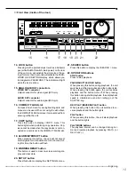
Page 12: ...playback speed and reversing or for warding the image 7 JOG dial Used to set various menus and search functions forwarding or reversing the image during playback field by field 8 SPLIT SEQUENCE button Press the button to display SPLIT4 SPLIT9 screen or SEQUENCE screen setting on multiplexer func tions 9 ZOOM button When pressing this button once during single screen display the screen is magnified...

Page 13: ...button will flash 19 WARNING RESET button This button is used to clear on screen warning dis play and clear data 20 SET UP button Press this button to display the SETTINGS menu 21 SEARCH button Press this button to display the SEARCH menu 22 OPERATION buttons STOP button Press to stop playback PAUSE SHUTTLE HOLD button When pressing this button during playback the unit switches to still frame play...

Page 14: ...nnectors VIDEO OUT connector Output connector for video signal to monitor BNC connector S Y C OUT connector These are output connectors for video signals that separate brightness signals and color signals for higher picture quality Simultaneous output along with VIDEO OUT is provided 3 CAMERA IN connectors Input connector for signal of camera BNC connec tor 4 CAMERA OUT connectors Camera video out...

Page 15: ...ribed in the manual included with Compact Flash Card Inserting Card 1 Remove the COMPACT FLASH slot cover attached to the unit 2 Please turn down the side which contains notch in right and left securely insert the Card until the CFC EJECT button pops out Do not eject the Card when copying restoring copy ing loading menus or immediately after inserting the Card The Card or the contained data may be...

Page 16: ...32 ø0 65 mm AWG 28 22 Cut the designated area from the electric wire s outer covering vinyl portion 5 7mm To GND terminal To ALARM IN terminal corresponds to the CAMERA SENSOR 1 To MIC jack MICROPHONE CAUTION Connecting a coaxial transmission camera wrong may damage the input terminal Be careful CAUTION When a microphone is connected to the MIC jack the MIC jack will be given priority over the AUD...

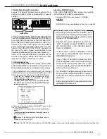
Page 17: ...icator is flashing Press the POWER button after the indicator turns off HDD CONFIGURATION HDD MASTER HDD 120GB SLAVE NONE POWER OFF INITIALIZE HDD REC MODE NORMAL ALL HDD DATA WILL BE ERASED 2 Turn the JOG dial to display INITIALIZE and turn the SHUTTLE ring clockwise SETTING UP appears on the screen and initialization starts When completed with initialization the display returns to the normal scr...

Page 18: ...E to 3 default 1 1 Set the MAIN switch on the rear of the unit to ON Press the POWER button on the front after the ACCESS indicator turns off SETTING UP appears on the screen and the unit is booted POWER button operation will not be accepted while the ACCESS indicator is flashing Press the POWER button after the indicator turns off 2 After boot up press the SET UP button inside the door on the fro...

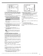
Page 19: ...the clock will either move forward or back one hour You can also always keep it ON or OFF as needed Use the JOG dial to flash AUTO the daylight saving function ac tivated Turn the SHUTTLE ring clockwise to enter the selection In the DAYLIGHT SETTING setting start end time of the DAYLIGHT SAVING function can be checked and changed Example Set the start time of the DAYLIGHT SAVING function IN to MON...

Page 20: ...isplay 18 and turn the SHUTTLE ring clockwise The setting is confirmed and flashing stops TIME DATE ADJUST DAYLIGHT SAVING OFF MONTH 10 DAY 28 YEAR 2003 TIME 18 00 00 The time is indicated using the 24 hour system 10 Repeat steps 8 and 9 to set MINUTE and SECOND 11 Turn the SHUTTLE ring clockwise The setting is confirmed and flashing stops TIME DATE ADJUST DAYLIGHT SAVING OFF MONTH 10 DAY 28 YEAR ...

Page 21: ...ding to the chart below Setting of GRADE default STD SUPER HIGH STD STANDARD BASIC LONG Example Set PPS of camera number 1 to 0 333P and GRADE to HIGH for normal recording 1 Press the SET UP button to display the SETTINGS screen 2 Turn the JOG dial to move the cursor to RECORD SETTINGS and turn the SHUTTLE ring clockwise The RECORD SETTINGS screen appears RECORD SETTINGS RECORD SETTING ALARM REC D...

Page 22: ...e previous playback STOP PAUSE REV PLAY PLAY When the HDD REPEAT PLAY setting in the HDD SETTINGS is set to OFF playback is stopped when reaching the end of the physical HDD or recorded section When the HDD REPEAT PLAY setting is set to ON recorded video data is played back repeatedly see HDD REPEAT PLAY page 43 1 1 Changing the playback device The default setting of the playback device is HDD Whe...

Page 23: ...ound of the setting item changes to red and flashes Turn the JOG dial to display the desired search menu and confirm Setting default TIME DATE TIME DATE INDEX ALARM INDEX ALARM SKIP ALARM LIST 11 When the setting is complete turn the SHUTTLE ring counterclockwise The display returns to the TIME DATE SEARCH screen and the cursor appears on the left of the search date 12 Turn the JOG dial to select ...

Page 24: ...below to change to another language Setting default ENGLISH ENGLISH FRANCAIS ESPAÑOL 1 Press the SET UP button SETTINGS Select LANGUAGE SELECTION in the INITIAL SET UP INFORMATION screen and display the desired setting INITIAL SET UP INFORMATION HDD SETTINGS AUDIO RECORDING OFF REAR TERMINAL SETTINGS RS 232C INFORMATION SERVICE LANGUAGE SELECTION ENGLISH 2 Turn the SHUTTLE ring counterclockwise or...

Page 25: ...k l mnopqrs t uvwxyz SHUTTLE GO BACK MPX DISPLAY SETTINGS SPLIT4 SCREEN SETTING SPLIT9 SCREEN SETTING SEQUENCE SETTING INTERLASE ON SPLIT4 SCREEN SETTING SPLIT4 a SPLIT4 b SPLIT4 c SPLIT9 SCREEN SETTING SPLIT9 SEQUENCE SETTING SEQUENCE NUMBER TIME 1 1S 2 1S 3 1S 4 1S 5 1S 6 1S 7 1S 8 1S 9 1S SPLIT4 abc 1S SET UP SUB MENU 1 TIME DATE DISPLAY SETTINGS Pages 18 20 30 31 TIME DATE ADJUST Page 20 MAIN ...

Page 26: ... MODE A ALARM PLUS NO PPS GRADE A PPS A GRADE 1 389P STD 1 389P STD 1 389P STD 1 389P STD 1 389P STD 1 389P STD 1 389P STD 1 389P STD 1 389P STD 1 389P STD 1 389P STD 1 389P STD 1 389P STD 1 389P STD 1 389P STD 1 389P STD 1 389P STD 1 389P STD ESTD REC D H M TIMER PROGRAM P1 DW START END MODE M DET 1 2 3 4 5 6 7 8 SPL SAT SUN HOLIDAY SETTING DAY MONTH SETTINGS TIME DATE DISPLAY SETTINGS MPX DISPLA...

Page 27: ... END INFORMATION SERVICE HDD INFORMATION CFC INFORMATION WARNING LOG LIST RESET TO FACTORY SETTING HDD DATA CLEAR CFC DATA CLEAR ELAPSED TIME 10H WARNING LOG LIST NO DATE TIME WARNING 0001 01 01 02 00 00 00 ALM ON INFORMATION HDD MASTER HDD 120GB SLAVE NONE START END SETTINGS TIME DATE DISPLAY SETTINGS MPX DISPLAY SETTINGS MOTION DETECTION SETTINGS RECORD SETTINGS TIMER PROGRAM SETTINGS INITIAL SE...

Page 28: ...FC INFORMATION WARNING LOG LIST RESET TO FACTORY SETTING HDD DATA CLEAR CFC DATA CLEAR ELAPSED TIME 10H HDD DATA CLEAR PUSH WARNING RESET KEY FOR 1 SECOND TO CLEAR CFC DATA CLEAR PUSH WARNING RESET KEY FOR 1 SECOND TO CLEAR SETTINGS TIME DATE DISPLAY SETTINGS MPX DISPLAY SETTINGS MOTION DETECTION SETTINGS RECORD SETTINGS TIMER PROGRAM SETTINGS INITIAL SET UP INFORMATION QUICK SETTINGS MEMO HDD CON...

Page 29: ...EY FOR SEARCH SELECTION ALARM SKIP SEARCH EXECUTE FORWARD EXECUTE REVERSE PUSH SEARCH KEY FOR SEARCH SELECTION ALARM INDEX SEARCH INDEX 01 EXECUTE FORWARD EXECUTE REVERSE START END PUSH SEARCH KEY FOR SEARCH SELECTION SEARCH SELECTION SEARCH TYPE ALARM LIST SELECTION CAMERA NO ALL DATE TIME PLAYBACK DEVICE HDD START 01 01 2002 00 00 00 END 01 01 2002 00 00 05 SEARCH SELECTION SEARCH TYPE INDEX PLA...

Page 30: ...ial to move the cursor to the desired display position and turn the SHUTTLE ring clockwise The setting is confirmed The cursor can be continuously moved vertically by turning the JOG dial 3 Turn the SHUTTLE ring counterclockwise or press the SET UP button CAMERA DISPLAY Setting can be made to display the title and memo set in CAMERA DISPLAY camera number only etc TIME DATE DISPLAY SETTINGS TIME DA...

Page 31: ... character input turn the SHUTTLE ring counterclockwise The display returns to the CAMERA TITLE MEMO SETTING screen 9 7 4 5 6 1 2 3 8 CAMERA TITLE MEMO SETTING ENTRANCE COUNTER MEMO BANK SHUTTLE CHARACTERS Example CAMERA TITLE MEMO SETTING 8 Repeat steps 2 7 to set camera number 4 and memo 9 Turn the SHUTTLE ring counterclockwise or press the SET UP button 03 03 2003 21 25 40 ENTRAN COUNTE Example...

Page 32: ...n display of the pressed camera number button Pressing the SPLIT SEQUENCE button again returns the screen to the split sequential display previous to cancelling When a menu screen and split sequential display are displayed simultaneously the single screen dis play will not appear even when pressing a camera number button In this case clear the menu screen and then press a camera number button 1 9 ...

Page 33: ...ra number selected in MPX DISPLAY SETTINGS SPLIT9 SCREEN SETTING screen is displayed using SPLIT9 display During video display the corresponding camera number button lights The video of camera number selected in MPX DISPLAY SETTINGS SPLIT4 SCREEN SETTING screen is displayed using SPLIT4 display During video display the corresponding camera number button lights The single screen video set in MPX DI...

Page 34: ...ber reverses in color 3 Turn the JOG dial to the desired camera number and select it by turning the SHUTTLE ring clockwise The background of the camera number turns red and flashes 4 Turn the JOG dial to change to the desired camera number and select it by turning the SHUTTLE ring Flashing stops The same camera number can be selected mul tiple times to a split screen display However only a single ...

Page 35: ...TINGS Select INTERLASE in the MPX DISPLAY SETTINGS screen Display the desired setting and confirm 2 Turn the SHUTTLE ring counterclockwise or press the SET UP button In this menu the conditions of the motion detection func tion for alarm recording which is started when detecting motion within the video of the connected camera are set SELECTION CAMERA NUMBER The camera for motion detection setting ...

Page 36: ...n the JOG dial The active setting changes to inactive setting When pressing the SPLIT SEQUENCE button all dots change to active When pressing the ZOOM button all dots change to inactive 4 Repeat step 3 to activate inactivate all desired dots 5 Turn the SHUTTLE ring counterclockwise The setting is confirmed and the display returns to the MOTION DETECTION SETTINGS screen During set detection mask se...

Page 37: ...than Motion detection will not operate while making settings in the MOTION DETECTION SETTINGS MOTION THRESHOLD The minimum number of dots for starting the motion de tection operation from the number of active dots within the detection area is set here Motion detection operates when change that exceeds the number of minimum dot set is detected 1 MOTION DETECTION SETTINGS SELECTION CAMERA NUMBER MOT...

Page 38: ...ording is performed for only the cameras set for alarm recording and activated via alarm signals When there is input of alarm signals from multiple cameras alarm recording is performed for all cameras containing alarm signals ALARM PLUS Recording is performed in the frame speed set in A PPS for the camera inputted with alarm signals during normal recording All other cameras will be recording in th...

Page 39: ...ET UP button PRE ALARM REC The pre alarm recording can be set ON OFF and the record ing time during pre alarm recording can be set here RECORD SETTINGS RECORD SETTING ALARM REC DURATION 5S PRE ALARM REC OFF Setting default OFF OFF SHORT MEDIUM LONG For details concerning pre alarm recording time see Pre alarm recording time table pages 68 69 When PRE ALARM REC is active LONG MEDIUM or SHORT change...

Page 40: ...t day of the week and end day of the week set here are active Example Using program 1 in TIMER PROGRAM P2 REC MODE A will record to Wednesday Saturday from 12 30 to 13 00 and M DET is set to ON 1 Press the SET UP button SETTINGS Select TIMER PROGRAM SETTINGS screen TIMER PROGRAM SETTINGS SELECTED PATTERN P1 SET HOLIDAY SETTING REC MODE A NORMAL ALARM SET REC MODE B NORMAL ALARM SET REC MODE C NORM...

Page 41: ...reen and return to the normal screen If there is an unset item with in the program display the setting screen cannot be exited even when turning the SHUTTLE ring counterclockwise In this case set all unset items 20 Press the TIMER button The TIMER button lights Timer recording starts if the current time is within the timer reservation time frame The power turns off and recording will be in the sta...

Page 42: ...P Program 1 Program 1 Example 2 Program 1 is set for 14 00 to 17 00 with the PPS to 5P Program 2 is set for 15 00 to 16 00 with the SKIP setting Again the unit will give priority to Program 2 for the duration of the overlapping period As shown in the illustration below the unit will activate the Skip setting from 15 00 to 16 00 14 00 15 00 16 00 17 00 14 00 15 00 16 00 17 00 5P 5P NO RECORDING Exa...

Page 43: ...ROR 1 2 3 HDD SETTINGS HDD REPEAT REC The operation when HDD Hard Disk Drive space becomes full during recording is set HDD SETTINGS HDD REPEAT REC OFF HDD REPEAT PLAY OFF IM CHECK PLAY OFF SEQUENTIAL PLAY OFF Setting default OFF ON Automatically returns to the beginning of the HDD and resumes recording by overwriting old data STANDBY When the HDD space becomes full recording is stopped and the un...

Page 44: ...ary select NONE in the CAMERA DIS PLAY see page 30 AUDIO RECORDING This unit can record audio and video for one channel Because audio recording takes HDD space when recording audio HDD space is less than when recording only video INITIAL SET UP INFORMATION HDD SETTINGS AUDIO RECORDING OFF REAR TERMINAL SETTINGS RS 232C INFORMATION SERVICE Setting default OFF ON Records video and audio ALARM During...

Page 45: ...GS EMERGENCY REC DURATION 10M 1 Press the SET UP button SETTINGS INITIAL SET UP INFORMATION Select KEY SOUND in the REAR TERMINAL SETTINGS screen Display the desired setting and confirm 2 Turn the SHUTTLE ring counterclockwise or press the SET UP button BUZZER It is possible for a buzzer to sound when the remaining HDD space reaches the value set in REMAIN HDD of the REAR TERMINAL SETTINGS screen ...

Page 46: ...lashing stops 5 Turn the SHUTTLE ring counterclockwise or press the SET UP button CALL OUT SETTINGS The CALL OUT setting is a setting used to notify via the rear terminals when a warning signals is activated The warning signal can be activated by a malfunction or a HDD setting being monitored To reduce miswiring the CALL OUT terminal output is a photo coupler output see page 16 CALL OUT output ter...

Page 47: ...he unit Note no video is transmitted REMOTE B This unit can be controlled from a PC and status condition change information is not returned from the unit Note no video is transmitted OFF This unit cannot be controlled from a PC 1 Press the SET UP button SETTINGS INITIAL SET UP INFORMATION Select MODE in the RS 232C screen Display the desired setting and confirm 2 Turn the SHUTTLE ring counterclock...

Page 48: ...AL SET UP INFORMATION Select WARNING LOG LIST in the INFORMATION SERVICE screen Turn the SHUTTLE ring clockwise The WARNING LOG LIST screen appears The WARNING LOG LIST can display up to 1000 items When the number of items exceed this limit the latest 1000 items are displayed button turn JOG dial counterclockwise Selection moves to the next number button turn JOG dial clockwise Selection moves to ...

Page 49: ...OAD SETTING DATA FROM CFC SAVE SETTING DATA TO CFC 3 Select LOAD SETTING DATA FROM CFC and turn the SHUTTLE ring clockwise The SETTING DATA LOADING screen appears To cancel the update of menu settings turn the SHUTTLE ring counterclockwise SETTING DATA LOADING LOADING SHUTTLE EXECUTE GO BACK 4 Turn the SHUTTLE ring clockwise The menu settings of this unit is updated and COMPLETED appears on the sc...

Page 50: ...etting see pages 40 42 SELECTED PATTERN P1 REC MODE A NORMAL ALARM REC MODE B NORMAL ALARM TIMER PROGRAM SETTINGS SELECTED PATTERN P1 SET HOLIDAY SETTING REC MODE A NORMAL ALARM SET REC MODE B NORMAL ALARM SET REC MODE C NORMAL ALARM SET REC MODE D NORMAL ALARM SET ALARM REC DURATION 5S PRE ALARM REC SHORT 5 REC MODE A screen setting see page 42 All cameras 1 9 PPS GRADE Set desired interval and p...

Page 51: ... HDD REPEAT REC ON HDD SETTINGS HDD REPEAT REC ON HDD REPEAT PLAY OFF IM CHECK PLAY OFF SEQUENTIAL PLAY OFF 4 TIMER PROGRAM SETTINGS screen setting see pages 40 42 SELECTED PATTERN P2 REC MODE A NORMAL ALARM REC MODE B NORMAL ALARM HOLIDAY SETTING 12 31 01 01 01 02 01 03 TIMER PROGRAM SETTINGS SELECTED PATTERN P2 SET HOLIDAY SETTING REC MODE A NORMAL ALARM SET REC MODE B NORMAL ALARM SET REC MODE ...

Page 52: ... OUT 4 OFF KEY SOUND ON BUZZER OFF REMAIN HDD HDD 10 CALL OUT SETTINGS EMERGENCY REC DURATION 20M 3 Set each item in the MOTION DETECTION SET TINGS screen for all cameras see pages 35 37 SELECTION CAMERA NUMBER MOTION DETECTION Set operation to ON or OFF for all cameras 1 MOTION DETECTION SETTINGS SELECTION CAMERA NUMBER MOTION DETECTION OFF DETECTION MASK SETTING SENSITIVITY HIGH LOW MOTION THRES...

Page 53: ... NO 3 SAT 08 00 08 00 D ON PROGRAM NO 4 SUN 08 00 08 00 D ON TIMER PROGRAM P3 DW START END MODE M DET 1 SPL 08 00 15 00 C ON 2 SPL 15 00 08 00 D ON 3 SAT 08 00 08 00 D ON 4 SUN 08 00 08 00 D ON 5 6 7 8 SPL MON FRI When completed with all settings above and after clear ing the menu screen press the TIMER button The unit will switch to the timer mode ...

Page 54: ...re quality SUPER 2 Cameras used Recording is performed using all cameras other than those set to in PPS and in A PPS During timer recording recording is performed using all cameras other than those set to in the recording mode of the set time frame 3 During recording The EMERGENCY indicator flashes and then lights when recording is completed To turn off the indicator display the ALARM LIST SEARCH ...

Page 55: ...firm Set the number of the connected MODE OUT terminal When not overwriting data on the first unit this setting is not required for the second unit 3 Display HDD 20 in REMAIN HDD of the same screen and confirm REAR TERMINAL SETTINGS MODE OUT 1 REMAIN MODE OUT 2 REMAIN MODE OUT 3 REMAIN MODE OUT 4 REMAIN KEY SOUND ON BUZZER OFF REMAIN HDD HDD 20 CALL OUT SETTINGS EMERGENCY REC DURATION 10M If not o...

Page 56: ...ce in the single screen mode the frame advance operation may not operate cor rectly when the JOG dial is turned too fast This is because when advancing is performed the unit is actually searching for the video of the display camera number Reverse playback 1 Press the REV PLAY REVERSE PLAYBACK button while playback is stopped Playback will be made in the reverse direction Playback will stop when pr...

Page 57: ...isplay mode with 2 or 3 set in DISPLAY MODE in the TIME DATE DISPLAY SETTINGS screen the play back interval is displayed on the screen in green for easy confirmation if the value is changed Monitor display settings and playback operation Single screen The screen will change frame by frame at a rate equal to the recording interval multiplied by the number of cameras used in the recording SPLIT4 Eac...

Page 58: ...00 00 00 END 04 04 2003 12 30 15 Setting default ALL ALL 1 2 3 4 5 6 7 8 9 ALL Search is conducted for all camera number 1 9 and search results are displayed in SPLIT9 screen 1 9 When SEARCH TYPE is set so that it is possible select the camera numbers the unit ex ecutes the search corresponding the specified con ditions from the selected cameras and the search result is displayed on the SINGLE scr...

Page 59: ...erforming INDEX SEARCH ALARM INDEX SEARCH SPLIT9 screen is always displayed for INDEX SEARCH For ALARM INDEX SEARCH SPLIT9 screen is displayed when setting the above SELECTION CAMERA NO to ALL Single screen with still frame playback is displayed when selecting individual camera number INDEX SEARCH INDEX 01 EXECUTE FORWARD EXECUTE REVERSE START 02 02 2003 00 00 00 END 04 04 2003 12 30 15 PUSH SEARC...

Page 60: ...rd direction EXECUTE REVERSE Search is performed in the reverse direction To cancel the search press the SEARCH button twice Playback of search result from skip search will be in SPLIT9 display regardless of whether the above SELECTION CAMERA NO is set to ALL or individual camera number is selected To return to the normal screen press the SEARCH button twice Press the desired camera number button ...

Page 61: ...list When setting HDD REPEAT REC to OFF or STANDBY and there is an alarm recording emer gency recording at the end of the HDD that record ing may not be stored in the alarm list When alarm recording emergency record ing is performed during display of the ALARM LIST SEARCH screen exit the ALARM LIST SEARCH screen and display the Alarm screen again The new item will be added to the list When using D...

Page 62: ...ether the data in the Compact Flash Card is recording data or menu data 5 Display the desired setting in TRANSFER PERIOD and confirm Setting default START END START END Sets the recording start end date time START Sets the recording start date time 6 Set the desired copy restore start date and time to START and confirm 7 When setting START END in step 5 Set the desired copy restore end date and ti...

Page 63: ...OCK which does not require a password to unlock and PASSWORD LOCK which require a password to unlock If the password for unlocking has not been set Lock function will be SIMPLE LOCK If the password for unlocking has been set Lock function will be PASSWORD LOCK When the MAIN switch on the rear of the unit is set to ON SIMPLE LOCK PASSWORD LOCK can be activated even with the POWER button on the fron...

Page 64: ...nge and repeat steps 3 and 4 6 Turn the JOG dial to move the reverse display to CONFIRM and turn the SHUTTLE ring clockwise SECOND appears and the first input position is displayed in reversed color PASSWORD LOCK SETTING SET PASSWORD FIRST SECOND CONFIRM JOG SELECT INPUT PLACE SHUTTLE CONFIRM INPUT PLACE SELECT CONFIRM AND SHUTTLE TO CONFIRM PASSWORD To exit the screen when setting the PASSWORD LO...

Page 65: ...A SETTING to OFF the playback video will not be displayed and will appear in the display section of the corre sponding camera Furthermore the operation mode display and alarm display setting will not function 1 Press the SET UP button and select SETTINGS With the MPX DISPLAY SETTINGS screen displayed press the WARNING RESET button for more than 5 seconds The COVERT CAMERA SETTING screen appears 9 ...

Page 66: ...h 1d23h 2d23h 4d14h 6d15h 11d12h 2d23h 4d10h 6d14h 9d14h 17d6h 3d23h 5d18h 8d15h 12d5h 21d10h 4d17h 6d23h 10d13h 14d20h 25d4h 5d16h 8d8h 12d10h 17d6h 28d15h 9d 13d1h 18d10h 25d4h 38d17h 12d19h 18d5h 24d23h 33d2h 47d6h 22d11h 29d16h 37d19h 47d6h 59d9h 37d1h 44d23h 52d22h 59d9h 67d12h 124d5h 183d15h 291d16h 432d2h 864d5h 248d11h 367d7h 583d8h 864d5h 1728d11h Continuous recordable time and the estima...

Page 67: ... using 12 8KHz PCM sampling is possible PPS GRADE SUPER HIGH STD BASIC LONG h hour m minute s second 30P 15P 10P 7 5P 6P 5P 3P 2P 1P 0 5P 0 25P 0 125P 40s 1m 1m40s 2m30s 4m10s 1m30s 2m10s 3m20s 4m50s 8m20s 2m10s 3m20s 4m50s 7m 12m 3m 4m10s 6m20s 9m 15m 3m30s 5m10s 7m50s 10m 18m 4m10s 6m10s 9m10s 12m 21m 6m50s 9m40s 13m 18m 28m 9m50s 13m 18m 24m 34m 16m 22m 28m 35m 44m 27m 33m 39m 45m 51m 1h30m 2h1...

Page 68: ... RECORDING FIELD PPS GRADE SUPER HIGH STD BASIC LONG 30P 15P 10P 7 5P 6P 5P 3P 2P 1P 0 5P 0 25P 0 125P m minute s second 1 5s 2 3s 3 6s 5 3s 10s 3 1s 4 6s 7 3s 10s 21s 4 8s 7s 11s 16s 32s 6 3s 9 3s 14s 21s 42s 7 9s 11s 18s 26s 53s 9 6s 14s 22s 32s 1m 15s 23s 36s 53s 1m40s 24s 35s 55s 1m20s 2m40s 48s 1m10s 1m50s 2m40s 5m20s 1m30s 2m20s 3m40s 5m20s 10m 3m10s 4m40s 7m20s 10m 21m 6m20s 9m20s 14m 21m 4...

Page 69: ... 10s 14s 25s 6 1s 8 7s 13s 18s 31s 7 3s 10s 15s 22s 37s 8 8s 12s 18s 26s 42s 13s 19s 27s 37s 57s 20s 28s 38s 50s 1m10s 34s 46s 58s 1m10s 1m30s 56s 1m 1m20s 1m30s 1m40s 3m10s 4m40s 7m20s 10m 21m 6m20s 9m20s 14m 21m 42m With Audio recording recording duration SHORT PPS GRADE SUPER HIGH STD BASIC LONG 30P 15P 10P 7 5P 6P 5P 3P 2P 1P 0 5P 0 25P 0 125P m minute s second 0 7s 1 1s 1 7s 2 5s 4 2s 1 5s 2 ...

Page 70: ...om the selected camera Check this by setting the unit to SPLIT9 Is the connecting cord connected correctly Is the camera s focus adjusted correctly Is the HDD REPEAT REC set to OFF or STANDBY The unit begins recording only after the specified recording time Was the unit stopped during the specified recording time Is the PRE ALARM REC indicator light on Is the LOCK indicator light on During normal ...

Page 71: ...TINGS screen larger than the value set in DETECTION MASK SETTING Is the RS 232C SETTINGS set correctly Are the unit and computer connected correctly Is there a defect in the connecting cable Is the proper connecting cable being used The screens of camera number with no video signal input will be blue even when setting for operation Is the POWER button flashing The unit cannot be operated when the ...

Page 72: ...ompact Flash Card No Compact Flash Card has been inserted Video signal was lost for more than 5 seconds during recording Video data that has been altered was played back System error has occurred Error has occurred during reading writing of data to HDD media Unable to recognize HDD Issued when in a high temperature environment within the tolerance level One HDD could not be detected during mirrori...

Page 73: ...ata input from all the connected cameras is recorded sequentially at a rate of number of cameras x recording interval 30P recording interval during normal recording C4 2 C3 2 C2 2 C1 2 C4 1 C3 1 C2 1 C1 1 30P 1 second 1 second 12 00 01 12 00 02 12 00 03 C1 3 Recording interval of camera Examples of time displayed during playback 30P 30P Hard disk drive HDD Storage device using the same magnetic re...

Page 74: ...op time for one week x 3set Memory Backup Lasts for more than 1 month CONNECTORS ALARM IN 1 9 Input Terminal for starting alarm recording CLOCK ADJ Input Terminal for adjusting clock REC Input Terminal for start recording EMERGENCY Input Terminal for start emergency recording GND Terminal for ground MODE OUT 1 4 Output Terminal for indication of recording selected mode DC 5V OUT Output Terminal fo...

Page 75: ...75 Specifications ...

Page 76: ...872C276A8 PRINTED IN MALAYSIA ...

Reviews: