16
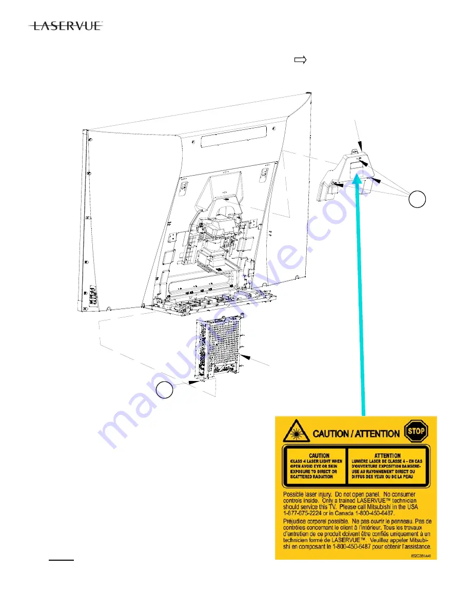
Electrical Chassis Removal
1. Disconnect all cables connecting to the chassis.
2. Remove
screw
(B).
3. Slide the chassis up and out of the cabinet.
Note:
After replacing either the Electrical Chassis or PWB-MAIN,
see Data Transfer section and perform the following procedures:
1. Restore Engine Data From Backup
2. Restore Geometry Data From Backup.
3. Restore ISF Settings From Backup (Only if backup USB
memory device is available).
IMPORTANT REPLACEMENT NOTE:
If the customer has sub-
scribed to VUDU (Internet program provider), the customer must be
instructed to contact VUDU to re-activate their account after a re-
placement CHASSIS or PWB-MAIN has been installed. The original
part
cannot
be installed in another TV. It must be returned to Mitsu-
bishi per policy.
Service Cover Removal
(For Light Source Unit and Optical Engine Replacement)
1. Remove screws (A) indicated on the Service Cover by the arrows
2. Remove the Service Cover in the direction indicated.
SERVICE
COVER
ELECTRICAL
CHASSIS
A
B
Summary of Contents for DLP WD-82CB1
Page 2: ......
Page 4: ...4 ...
Page 9: ...9 Introduction ...
Page 69: ...DLP HOME CINEMA 69 CIRCUIT BLOCK DIAGRAMS ...
Page 70: ...DLP HOME CINEMA 70 CIRCUIT BLOCK DIAGRAMS ...
Page 71: ...DLP HOME CINEMA 71 ...
Page 72: ...DLP HOME CINEMA 72 ...
Page 73: ...DLP HOME CINEMA 73 ...
Page 74: ...DLP HOME CINEMA 74 ...
Page 75: ......


