


Installation and connectionInstallation 2-22
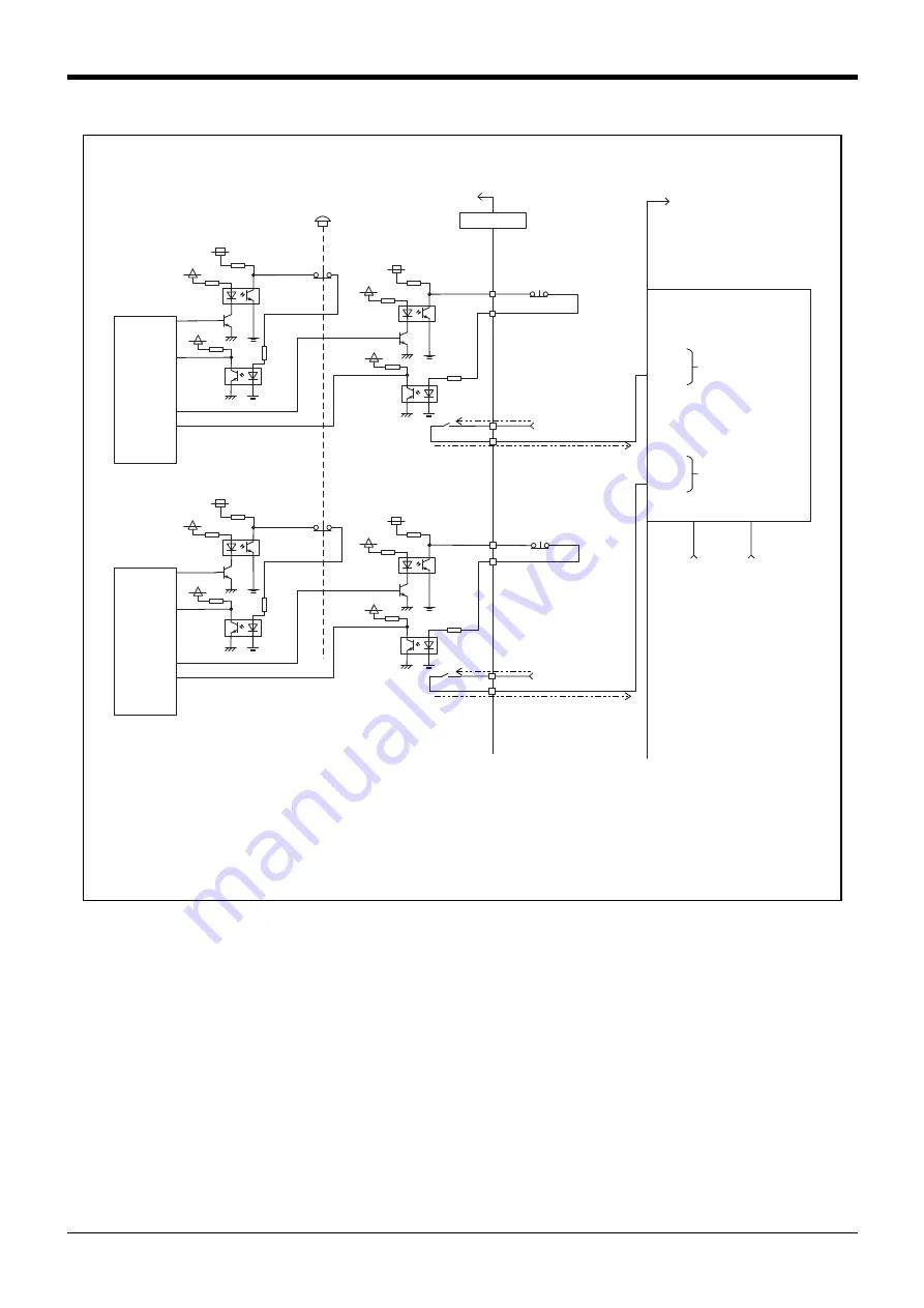
Fig.2-15 : Examples of safety measures (Wiring example 6)
10
26
3
19
14
30
7
23
No connection
No connection
COM0
X0
COM1
+24V
24G
24V DC
24V DC
24V DC
24V G
X1
Controller
T/B emergency stop switch
Customer equipment
Safety relay
Safety input 1
Safety input 2
Customer power supply
(DC 24V)
Example)
QS90SR2SP (Mitsubishi
Electric Corporation)
External emergency
stop switch
External emergency
stop switch
Internal
emergency
stip input
1
Internal
emergency
stip input
2
Emergency stop
output
Emergency stop
output
CNUSR11
+24V
+24V
+3.3V
+3.3V
+3.3V
+24V
+3.3V
+3.3V
+3.3V
+24V
+3.3V
+3.3V
<Wiring example 6>: Connecting a safety relay to a robot controller
The emergency stop switch of the controller is used as an input to the safety relay.
[Caution]
1) When connecting a safety relay to the system and using the emergency stop switch of the controller as an input to the relay,
select a safety relay that functions when a signal is input to either one of the two input points. (Example: QS90SR2SP
(manufactured by Mitsubishi Electric))
2) When connecting the output of the emergency stop switch to an external safety relay, set the polarity so that the electric
current flows in the direction as indicated by the dotted arrows in the wiring diagram above. If the polarity is set incorrectly,
this function will not operate correctly.
Please connect 3 and 10 terminal of CNUSR11 connector to 24V.


