24
GB
Please observe the following precautions during installation.
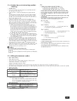
8.1. Precautions during installation
The water pressure resistance of the water pipes in the heat source unit is
2.0MPa [290psi].
Use the reverse-return method to insure proper pipe resistance to each unit.
3URYLGHVRPHMRLQWVDQGEXOEVDURXQGLQOHWRXWOHWRIHDFKXQLWIRUHDV\
maintenance, checkup, and replacement.
To protect the heat source unit, install a strainer on the circulating water inlet
pipe within 1.5 m [4-7/8in] from the heat source unit.
,QVWDOODVXLWDEOHDLUYHQWRQWKHZDWHUSLSH$IWHUÀRZLQJZDWHUWKURXJKWKH
pipe, vent any excess air.
Water may collect in the low-temperature sections of heat source unit. Add a
drainage pipe to the drain valve at the base of the unit to drain the water.
,QVWDOODEDFNÀRZSUHYHQWLRQYDOYHRQWKHSXPSDQGDÀH[LEOHMRLQWWR
prevent excess vibration.
Use a sleeve to protect the pipes at the point where they go through a wall.
6HFXUHWKHSLSHVZLWKPHWDO¿WWLQJSRVLWLRQLQJWKHPLQORFDWLRQVWRSURWHFW
pipes against breakage and bending.
Do not confuse the water intake and outlet valves.
This unit doesn’t include a heater to prevent freezing within tubes. If the
ZDWHUÀRZLVVWRSSHGRQORZDPELHQWGUDLQWKHZDWHURXW
The unused knockout holes should be closed and the refrigerant pipes,
water pipes, power source and transmission wires access holes should be
¿OOHGZLWKSXWW\
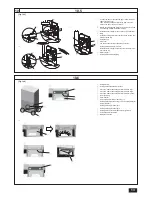
7KHGUDLQSOXJLVLQVWDOOHGRQWKHEDFNRIWKHXQLWDWIDFWRU\IRU¿HOG
connection of the drain pipes on the front of the unit. Move the plug to the
front to connect the drain pipes on the back. Verify that there are no leaks
from pipe connections.
For installing two units, install water pipes in parallel to each other so that the
ZDWHUÀRZUDWHWKURXJKERWKXQLWVZLOOEHHTXDO
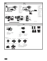
Wrap sealing tape as follows.
1
:UDSWKHMRLQWZLWKVHDOLQJWDSHIROORZLQJWKHGLUHFWLRQRIWKHWKUHDGV
FORFNZLVHGRQRWZUDSWKHWDSHRYHUWKHHGJH
2
Overlap the sealing tape by two-thirds to three-fourths of its width on
HDFKWXUQ3UHVVWKHWDSHZLWK\RXU¿QJHUVVRWKDWLWLVWLJKWDJDLQVWHDFK
thread.
3
Do not wrap the 1.5th through 2nd farthest threads away from the pipe
end.
Hold the pipe on the unit side in place with a spanner when installing the
pipes or strainer. Tighten screws to a torque of 150 N.
PNJāFP
When connecting heat source unit water piping and on site water piping,
apply liquid sealing material for water piping over the sealing tape before
connection.
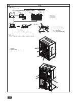
Example of heat source unit installation (using left piping)
[Fig. 8.1.1] (P.3)
A
Main circulating water pipe
B
Shutoff valve
C
Shutoff valve
D
:DWHURXWOHWXSSHU
E
Refrigerant pipes
F
Y-type strainer
G
:DWHULQOHWORZHU
H
Drain pipe
8.2. Insulation
installation
As long as the temperature range of the circulating water is kept to average
temperatures year-round (30 °C [86 °F] in the summer, 20 °C [68 °F] in the
ZLQWHUWKHUHLVQRQHHGWRLQVXODWHWKHLQGRRUSLSLQJ,QVXODWLRQVKRXOGEH
installed in the following situations:
On any heat source piping.
Indoor piping in cold-weather regions where frozen pipes are a problem.
When air coming from the outside causes condensation to form on piping.
On any drainage piping.
8.3. Water processing and water quality
control
To preserve water quality, use the closed type of cooling tower. When the
circulating water quality is poor, the water heat exchanger can develop scales,
leading to a reduction in heat-exchange power and possible corrosion. Pay
careful attention to water processing and water quality control when installing
the water circulation system.
5HPRYLQJRIIRUHLJQREMHFWVRULPSXULWLHVZLWKLQWKHSLSHV
'XULQJLQVWDOODWLRQPDNHVXUHWKDWIRUHLJQREMHFWVVXFKDVZHOGLQJ
fragments, sealant particles, or rust, do not enter the pipes.
Water Quality Processing
1
Depending on the quality of the cold-temperature water used in the air
conditioner, the copper piping of the heat exchanger may corrode.
Regular water quality processing is recommended.
Cold water circulation systems using open heat storage tanks are
particularly prone to corrosion.
When using an open-type heat storage tank, install a water-to-water heat
exchanger, and use a closed-loop circuit on the air conditioner side. If a
water supply tank is installed, keep air contact to a minimum, and keep
WKHOHYHORIGLVVROYHGR[\JHQLQWKHZDWHUQRKLJKHUWKDQPJƐ
2
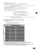
Water quality standard
Items
Low to mid-range
temperature water system
Tendency
Recirculating
water
[20<T<60°C]
[68<T<140°F]
Make-up
water
Corrosive
Scale-
forming
Standard
items
S+&>)@
7.0 ~ 8.0
7.0 ~ 8.0
c
c
(OHFWULFFRQGXFWLYLW\ P6P&>)@
ȝVFP&>)@
30 or less
[300 or less]
30 or less
[300 or less]
c
c
&KORULGHLRQ
PJ&OƐ
50 or less
50 or less
c
Sulfate ion
(mg SO4
2-
Ɛ
50 or less
50 or less
c
$FLGFRQVX
(mg
CaCO
3
Ɛ
50 or less
50 or less
c
Total hardness (mg CaCO
3
Ɛ
70 or less
70 or less
c
Calcium hardness (mg CaCO
3
Ɛ
50 or less
50 or less
c
Ionic silica
(mg SiO
2
Ɛ
30 or less
30 or less
c
Refer-
ence
items
,URQ
PJ)HƐ
1.0 or less
0.3 or less
c
c
&RSSHU
PJ&XƐ
1.0 or less
0.1 or less
c
6XO¿GHLRQ
PJ6
2-
Ɛ
not to be
detected
not to be
detected
c
Ammonium ion
(mg NH
4
+
Ɛ
0.3 or less
0.1 or less
c
5HVLGXDOFKORULQH
PJ&OƐ
0.25 or less
0.3 or less
c
Free carbon dioxide
(mg CO
2
Ɛ
0.4 or less
4.0 or less
c
Ryzner stability index
–
–
c
c
Reference : Guideline of Water Quality for Refrigeration and Air Conditioning
(TXLSPHQW-5$*/(
8. Water pipe installation
7.1. Installation
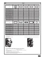
[Fig. 7.1.1] (P.2)
A
0DQFKRUEROW¿HOGVXSSOLHG
B
Check that the installation leg corners are securely supported to ensure that
the legs do not bend.
C
Check that the installation leg corners are securely supported.
Attach unit tightly with bolts so that it will not fall down due to earthquakes or
strong winds.
Use concrete or an angle bracket for the foundation.
Vibration may be transmitted to the installation area and noise and vibration
PD\EHJHQHUDWHGIURPWKHÀRRUDQGZDOOVGHSHQGLQJRQWKHFRQGLWLRQV
3URYLGHDPSOHYLEUDWLRQSURR¿QJFXVKLRQSDGVFXVKLRQIUDPHHWF
%HVXUHWKDWWKHFRUQHUVDUH¿UPO\DWWDFKHG,IWKHFRUQHUVDUHQRW¿UPO\
attach, the feet of the unit may be bent.
When using pads, be sure that the full width of the unit is covered.
7KHSURMHFWLQJOHQJWKRIWKHDQFKRUEROWVKRXOGEHOHVVWKDQPP>LQ@
The PQHY/PQRY-P·TLMU-A/YLMU-A should not be installed at outdoor.
Warning:
Install the unit in a location strong enough to withstand its weight.
Any lack of strength may cause unit to fall down, resulting in a
personal injury.
Have installation work in order to protect against strong winds and
earthquakes.
Improper installation may cause unit to fall down, resulting in a
personal injury.
:KHQEXLOGLQJWKHIRXQGDWLRQJLYHIXOODWWHQWLRQWRWKHÀRRUVWUHQJWKGUDLQZDWHU
GLVSRVDOGXULQJRSHUDWLRQGUDLQZDWHUÀRZVRXWRIWKHXQLW!DQGSLSLQJDQG
wiring routes.
7.2. Service
space
Allow for clearance space.
In case of a single unit installation, include 600 mm or more of space for
easier access when servicing the unit from back.
[Fig. 7.2.1] (P.2)
A
Space for removing the control box
B
Heat source unit
C
6HUYLFHVSDFHIURQW
7. Installation
Summary of Contents for CITY MULTI PQHY-P-TLMU-A
Page 55: ......


