background image

12   

NP180/160 Series Setup Manual


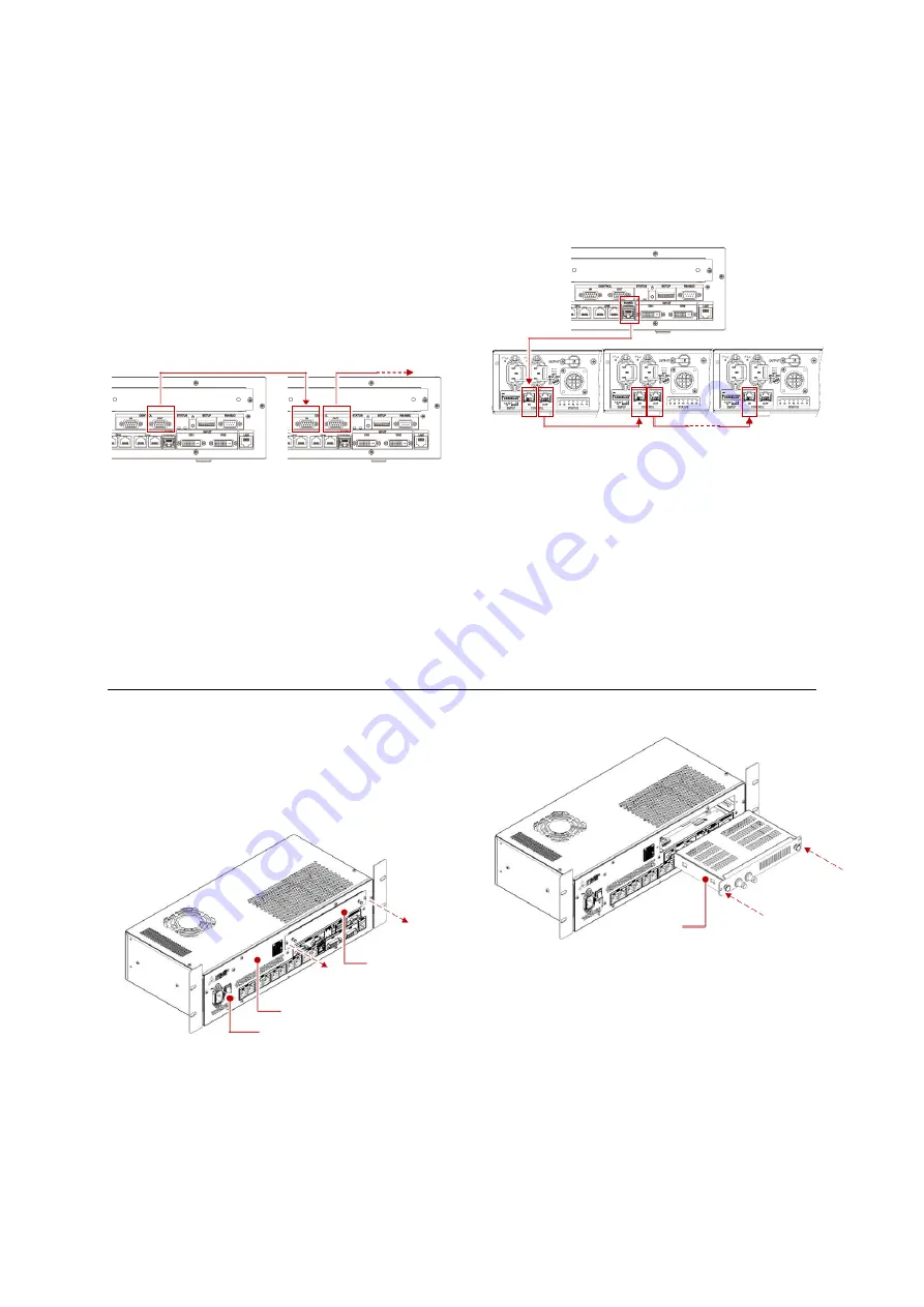
Between control units 

When using multiple control units, cascade them 
with the control cables that are supplied with the 
control units. 

1.


Connect  the  CONTROL  OUT  port  on  the 
master control unit (p. 20) and the CONTROL 
IN port on a slave control unit with the control 
cable. 

2.


Cascade all the slave control units in the same 
manner. 


It is not necessary to follow the control unit ID 
order (p. 32) to connect. 


In  case  that  the  supplied  control  cables  are 
short to connect depending on the control unit 
location,  extend  it  with  a  store-bought  cable 
(D-sub 9 pins, all connected, straight).  


Control  unit  to  power  units  (160 
Series) 

With  the  store-bought  network  cables  (p.  6)
connect  a  control  unit  and  the  power  units  that 
work for its displaying area. The control unit will be 
able to manage to turn on/off the power units. 


It  is  not  necessary  to  follow  the  power  unit  ID 
order (p. 19) to connect. 


When  the  power  unit  loop  is  connected  across 
control unit display area borders, the control unit 
manages  the  power  in  two  different  control 
displaying areas. 


Input board installation (when necessary)

Optional  input  boards  (p.  3)  can  be  added  as  an 
additional input source according to the necessity.  

1.


Be sure to turn off the main power switch of the 
control unit before installation. 

2.


Remove the cover panel. 


3.


Insert an input board and fix it with two screws. 


4.


OPS  computers  need  their  own  initial  setting  
(p. 37).


Input board 

Main power switch 

Cover panel 

Control unit 

Master 

Slaves 

Summary of Contents for 12NP180 Series

Page 1: ...Narrow Pixel Pitch Direct View LED NP180 Series NP160 Series Setup Manual Rev 2 2 March 29 2019 ...

Page 2: ...TING 19 DIP switch on power unit 160 Series 19 DIP switch on control unit 20 Turning on 21 Wallaby setup 22 2 BASIC SETTING 23 Configuration 23 Color calibration memory 26 System memory 28 Input memory 29 Display memory 30 Memory calling 31 3 ADVANCED SETTING WHEN NECESSARY 32 Detailed system memory setting 32 Detailed input memory setting 36 OPS computer setting 37 Wallaby menu bar 38 MAINTENANCE...

Page 3: ...P180R S NP1218FS S NP1218RS 15NP180F 15NP180R S NP1518FS S NP1518RS AC power cord Adapter to LED unit 2 m 5 m 8 m JC PC3AC2 JC PC3AC5 JC PC3AC8 For 160 Series Spare LED module 15NP160F 15NP160R S NP15FS S NP15RS DC power cord power unit to LED unit 2 m 5 m 8 m 12 m 15 m 20 m 30 m 60 m JC PC3DC2 JC PC3DC5 JC PC3DC8 JC PC3DC12 JC PC3DC15 JC PC3DC20 JC PC3DC30 JC PC3DC60 Redundant power unit S NP15PW...

Page 4: ...le connection p 10 Initial setting p 19 Configuration setting p 23 Auto color calibration p 26 Edge brightness compensation p 26 Manual color adjustment p 44 Luminous sensor run p 28 Input signal scanning p 29 Detailed Input signal setting p 36 Scaling setting p 30 Detailed system setting p 32 Finish ...

Page 5: ...akdown Be sure to mount demount the LED units by 2 or more people These works may be perilous particularly on a height or a narrow scaffold Unplug immediately if there is something wrong with your product Be careful not to twist or bend the LED surface Be careful not to bump or apply pressure on the LED surface and the edges Do not place the LED surface down In case you have to be sure to place it...

Page 6: ...it and the last cascaded power unit Necessary tools Hex key 5 mm Philips screwdriver 2 Wrench 13 mm for nuts that fix the adjustment screws Digital level Recommended accuracy 0 05 or finer length 600 mm or longer Spacers for edge protection at LED unit mounting S 160SP p 3 a set of 0 075 0 100 0 125 0 188 mm thickness spacers Recommended thickness when using store bought spacers 0 07 mm to 0 19 mm...

Page 7: ...ack height an example of 2x1 full HD resolution Numbers mentioned in this diagram are for a full HD resolution Store bought network cables p 6 Optional AC power cords from outlet Optional AC power cords Supplied AC power cords Supplied AC power cords x5 Network switch Wallaby Control unit x1 x10 VS 12NP180 VS 12NP180 D VS 12NP180 Network switch Wallaby x1 x1 x10 VS 12NP180 VS 12NP180 H x3 Adapter ...

Page 8: ...Numbers mentioned in this diagram are for a full HD resolution Store bought network cables p 6 Optional AC power cords from outlet Optional AC power cords Supplied AC power cords Supplied AC power cords Network switch Wallaby Control unit x1 x1 x1 x15 x6 x3 x3 Adapter x3 ...

Page 9: ...bers mentioned in this diagram are for a full HD resolution Store bought network cables p 6 Optional AC power cords Optional DC power cords Supplied DC power cords Supplied control cables x6 x15 x3 Power unit x3 Control unit x1 x6 x1 x1 x2 x1 Wallaby Network switch ...

Page 10: ...own display area as below Connect the cables to the associated LED units with each area 12NP 15NP CH 4 and 5 are not used in these models Connection rules One control unit displays up to the full HD resolution 1920 x 1080 pixels Multiple control units are needed for larger sizes Up to 64 control units can be cascaded in an LED wall They are two way traffic Even if one of the LED units fails in a l...

Page 11: ...12NP180FH or VS 12NP180RH is also counted as one unit The power units adapters can be connected to any LED units in any order The power unit adapter loop can be connected across control unit display area borders When connected across the borders do not use the active power peak saving function p 33 It wouldn t work properly Control lines Control unit to computer With the store bought network cable...

Page 12: ...eries With the store bought network cables p 6 connect a control unit and the power units that work for its displaying area The control unit will be able to manage to turn on off the power units It is not necessary to follow the power unit ID order p 19 to connect When the power unit loop is connected across control unit display area borders the control unit manages the power in two different cont...

Page 13: ...tallation Back side When installing the base stand leave a space behind the LED wall as described below or wider In addition to that if there is no dedicated air cooling equipment behind leave about 20 cm spaces above and underneath the LED wall for ventilation If the ventilation space is less forcibly exhaust the hot air with an air cooling device Surrounding front models All the installation wor...

Page 14: ... an impact or apply pressure on the LED surface and the edges It is recommended to properly put spacers p 6 on the LED edges for protection when mounting the LED units Due to the center of gravity the upper part of the LED units tends to lean to front Hold the upper handle as well as the lower dent to support 1 Prior to the mounting connect the necessary cables to the LED units that will be locate...

Page 15: ...accumulative assembling tolerance 3 Insert 2 supplied adjustment screws to the top part of the LED unit and lightly fix them with the supplied nuts from the other end 4 Place the second LED unit and fix it with 4 fixing screws lightly as the unit can still move The screw to fix their lower border can be inserted from either side 5 Turn the adjustment screws on the base stand to align the lower LED...

Page 16: ...g screws tightly 9 Repeat the steps to mount all the bottom row LED units 10 Prior to mounting the second bottom row recheck the level and leaning of the LED units as well as the linearity of the upper surfaces of the units Readjust them if inaccurate The targets are 0 level and 0 5 or less leaning measured with the digital level If there is no way to match the height of adjacent corner blocks lay...

Page 17: ...per LED units don t touch the edges of the lower LED units 14 Connect the inter connection cables from the lower LED unit to the upper unit To make sure if the cables are firmly connected it is recommended to display an image on the LED units Connect the power cords while the power is not supplied to the LED units p 21 15 Repeat the steps to complete all the LED unit mounting Even column Odd colum...

Page 18: ... of the LED units affect how the boundaries look Check it after displaying the 50 White test pattern for 10 minutes or longer 3 Compensate the edge brightness p 26 or adjust the gaps p 43 between the LED units according to the necessity Fixing to the wall and floor To prevent the LED wall from falling due to unpredictable events such as earthquakes or shocks fix them firmly to the back wall and th...

Page 19: ...ate On terminated Off Unit ID setting Assign unique ID numbers on the power units connected to each control unit The initial setting is ID 1 Up to 16 of ID numbers can be assigned with the DIP switches 1 to 4 Assign always from ID 1 For instance when you use 2 control units each of which has 3 power units 6 power units in total assign ID 1 to ID 3 for each ID 1 2 3 4 ID 1 2 3 4 1 9 2 10 3 11 4 12 ...

Page 20: ...the control unit is fixed as 192 168 100 XX The last byte the part of XX follows the setting of the DIP switches 1 to 4 in the range of 32 to 47 It can be used when the specified IP address is unclear and you can t hook up 2 With the DIP switches 1 to 4 the last byte of the IP address can be set in the range of 32 to 47 The ID numbers are automatically assigned linked with the setting Last byte ID...

Page 21: ...by p 24 C Set the Auto power on function ON in Wallaby p 33 The power is automatically supplied when the control unit is turned on 3 Once the power is supplied the two indicators light in green The LED units remain in black The image is displayed when an image source has been connected When the active power peak saving function p 33 is to be used due to lower total power distribution to the system...

Page 22: ...System memory p 28 The general setting of the LED wall The detailed setting menus p 32 can customize the LED wall more as necessary Input memory p 29 Scans input signals to display the image precisely Detailed setting by signal is also available according to the necessity Display memory p 30 sets displaying image sizes For instance a smaller resolution image can be displayed full screen on a bigge...

Page 23: ...eds to know the destination IP addresses Allocate the destination IP addresses that have been assigned on these control units p 20 When the Display Layout setting is applied the IP addresses and the ID numbers are automatically allocated in a sequential order from the upper left panel as below The initial starting IP address is 192 168 100 32 If you click the Sequential Numbering button with the S...

Page 24: ... the connection is establishment the connected panels will be in blue Otherwise the panels will be in gray Power On button starts supplying the power to the connected LED units p 21 LED unit location This function sets the location of the LED units and their ID numbers in each control unit 1 Click the Location and ID settings button The following window appears 2 Select the LED units to use and ch...

Page 25: ... of the LED units are saved click Cancel to exit the window 9 Display the Crosshatch internal test pattern p 38 The ID numbers have been properly set if it is displayed with no problem If not check the image signal cable connection and assign the ID numbers again Power unit count 160 Series According to the configuration enter the number of the connected power units to each control unit For a full...

Page 26: ...nge in sequence subjected to the progress Do not operate Wallaby during the process The test patterns can be displayed although it may take time to switch displaying 4 After confirming the process is completed close the Acquisition Calibration Data window with the Close button 5 The following window appears Select Yes to all to start transferring the values from all the control units to Wallaby If...

Page 27: ...n its both ends you can set different brightness level on each end Select Horizontal or Vertical in the Gradient mode and set different values in value 1 and 2 columns The values correspond to upper lower or left right You also can adjust one side of the border Click either side of the border to adjust after selecting the border To adjust the edge brightness on multiple control units adjust each s...

Page 28: ...ensor feedback menu accordingly To display a static image for a long period of time set it Run which corrects image persistence To display moving pictures or images that frequently change leave it Off as the correction effect would be less The sensor function periodically monitors the brightness and its lighting time of every single LED chip Using this data it automatically controls the luminance ...

Page 29: ...at click the button a few more times till the correct image will be displayed Window arrangement You can display the image in the specified size The display memory has the same setting p 30 Input memory saving The scanned input signals can be saved in the input memory The stored setting will be applied when the same image is displayed next time 128 memories are available After scanning or further ...

Page 30: ... input port to save in a display memory When you select Auto in the input memory column the input signal will be automatically scanned whenever input signals are switched over including resolution change Window arrangement Tile It displays the input signal full screen on each control unit display area Fit The image will be placed fitting the area in which you select When you select 2x2 area it mag...

Page 31: ...s to black which can be useful to turn off the images temporalily Display memory saving The adjusted display positions and sizes can be saved in a display memory 256 memories are available After adjustment surely click Save button in the display memory menu to store the setting in each control unit Specify a display memory number to save in and click Save in the window If the specified number has ...

Page 32: ...e 2 preset memories computer and video The User menu can customize the hue in the User setting menu The initial setting is OFF ID number If you connect over 16x control units you can allocate extended ID numbers on them Choosing 16 adds 16 on the number that has been set with the DIP switch on the control unit p 20 as ID 1 turns to ID 17 The ID can be set up to 64 The initial setting is 0 LAN sett...

Page 33: ... is OFF If a certain level of brighter content is detected in one of the control unit areas that have been set On all all these areas will be dimmed with keeping the uniformity among them Set the same percentage in the power control level column in these units Set the Frame lock function p 36 OFF when you use the On all setting On single setting dims only the brighter control unit area s When the ...

Page 34: ...unction Bigger values reduce the noise much while it tends to blur the entire image The initial setting is OFF Auto contrast It finds balance between brighter areas and darker areas in an image to improve the visibility on the darker areas Bigger values emphasize the details on the black parts in the image The initial setting is OFF When you use multiple control units to display one big image set ...

Page 35: ...ch picture quality It is the optimum value that shows the correct image without corruption even if you shift the value to adjacent figures Case 1 Set the Equalizer value 1 when the image is correctly displayed in Equalizer 0 1 and 2 Case 2 Set the Equalizer value 0 when the image is correctly displayed in Equalizer 0 and 1 but not in Equalizer 2 Optimum Equalizer value Quality in each Equalizer va...

Page 36: ...enus in the input memory Other settings than Auto the image is processed as specified without maintaining the original aspect ratio Signal type Signal types can be specified manually according to input signals Interlace When you display an interlace signal its precise scan mode can be selected manually Static for static images in interlace signals Adaptive for motion images in interlace signals Fi...

Page 37: ... booted up change the Power button settings to Shut down on Windows Control Panel All Control Panel Items Power Options System Settings 4 To improve the graphic performance install the graphic driver of the OPS computer 5 In Power Options change all the preferred power plans balanced power saver and high performance to Never in Dim the display Turn off the display and Put the computer to sleep 6 S...

Page 38: ...llaby Edit Read parameters Reads out the data in the selected control unit to update the data in Wallaby This operation is normally no need Wallaby automatically updates necessary data whenever it communicates with the control units Read Calibration Data from Control unit Reads out the color data in all the control units to Wallaby The Read from Control Unit menu in the Maintenance tab p 26 reads ...

Page 39: ...ED module to be replaced and temporarily tape them not to drop off The standard gap width between the LED modules are 0 125 mm for 12NP and 0 19 mm for 15NP Here thinner spacers than that are recommended to keep a certain adjustment margin 2 The spare LED modules are shipped in the condition to attach on the top left area in the LED unit Change the position of the screws behind the module accordin...

Page 40: ...uts anti clockwise till they stop The tool will attach to the LED module by magnetic attraction The magnetic plates don t touch the LED module directly and they don t scratch the surface of it 6 Rotate the outer knobs anti clockwise which loosen the screws behind the module 7 Detach the module 8 Disconnect 2 connectors on the back of the module 9 Leave the spacers as they will be used to attach th...

Page 41: ...ore recognizable if you light up the LED modules 14 Rotate the outer knobs clockwise to fix the LED module firmly 15 Reverse the step 5 to remove the tool 16 Remove the spacers 17 Adjust the color on the replaced LED module p 44 Rear maintenance models Each LED module is fixed with 3 screws from behind 1 Insert spacers p 6 on all 4 edges of the LED module to be replaced and temporarily tape them n...

Page 42: ...he steps to attach a new module Put the module in a precise location with careful attention not to hit the adjacent LED modules 6 Before fixing completely slightly move the position of the module to minimize the gaps evenly between the adjacent modules by means of thin spacers or similar The gap width can be more recognizable if you light up the LED modules 7 Fix the LED module firmly with the rem...

Page 43: ...ntenance models loosen 3 fixing screws located in the back side of the module 3 Insert the spacers into wider boundary and underneath the module The standard gap width between the LED modules are 0 125 mm for 12NP and 0 19 mm for 15NP Spacers with similar thickness are recommended for fine adjustment 4 Shift the module toward the spacers to be the optimum position as the LED chips are aligned hori...

Page 44: ...on in the Maintenance tab The confirmation window appears Click OK to start searching a new LED module If it finds out it automatically reads out the color data from it to the control unit 4 Next you need to transfer the collected color data from the control unit to Wallaby Click the Read from Control Unit button The following window appears Select Yes to start transferring the color data 5 In the...

Page 45: ...ws a crosshatched pattern on the actual display briefly so that you can check the location where you re adjusting p 27 10 Click the Send button on the bottom of the window to reflect the result on the LEDs 11 Repeat the step till you get an appropriate result You can modify multiple border values and the Send button reflects all the result at a time When replaced an LED module and a border on the ...

Page 46: ...you can replace it in the following way Front maintenance model 1 Remove all 4 LED modules p 39 2 Remove the center plate 3 Remove 12 screws and you can take out the tray that holds all the circuit boards Rear maintenance model Remove the back cover and you can reach all the circuit boards from behind 4x screws Back cover ...

Page 47: ...Information menu The detailed information of each unit is shown in the Information menu System status tab LED unit status In 180 Series the right click menu can turn on off each LED unit Power unit status 160 Series Error information tab ...

Page 48: ...Off Purple 9 Purple Purple Power unit 160 Series The power unit includes 4 power modules inside 5 modules in the optional redundant power supply S NP15PWR EX If one of the power modules fails the corresponding indicator goes off The S1 and S2 indicate the standby power Lighting either of them shows one of the power cords doesn t supply the power correctly or one of two standby power circuits fails...

Page 49: ...he operation procedure of the Sensor menu p 28 Added the chapter boundary adjustment p 43 Rev 1 2 Nov 9 2018 Added Wallaby update Rev 1 1 Jan 31 2018 The first edition Rev 1 0 Nov 30 2017 About trademarks HDBaseT and the HDBaseT Alliance logo are trademarks of the HDBaseT Alliance Intel is a trademark of Intel Corporation or its subsidiaries in the U S and or other countries Microsoft and Windows ...

Page 50: ......

Reviews: