22
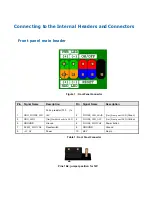
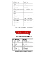
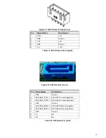
Figure 15:
SATA Power Cable pin-out
Pin
Signal Name
Description
1
VCC3
+3V
2
GND
Ground
3
VCC
+5V
4
GND
Ground
5
12V
+12V
Table 15:
SATA Power Cable signals
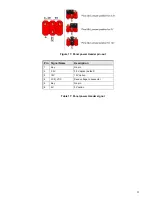
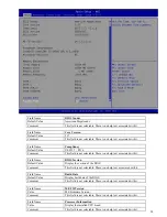
Figure 16:
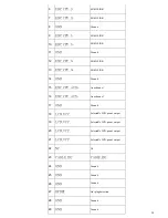
SATA Header pin-out
Pin Signal Name
Description
1
GND
Ground
2
SATAHDR_TXP0_C
SATA DATA Transmit(positive)
3
SATAHDR_TXN0_C
SATA DATA Transmit(negative)
4
GND
Ground
5
SATAHDR_RXN0_C
SATA DATA Receive(negative)
6
SATAHDR_RXP0_C
SATA DATA Receive(positive)
7
GND
Ground
8
G1
NC
9
G2
NC
Table 16:
SATA Header signals
Summary of Contents for Maestro 4070
Page 1: ...Maestro 4070 4080 User Manual Version 1 1 ...
Page 3: ...3 Speakers High definition sound quality brings you to enjoy great music world ...
Page 5: ......
Page 7: ...MB Information MB PH11CMI ...
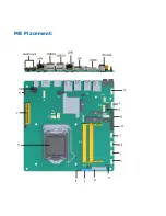
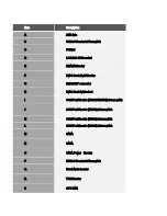
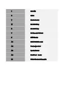
Page 8: ...MB Placement ...
Page 20: ...20 Figure 13 M 2 M key slot For Storage pin out Table 13 M 2 M key slot For Storage signals ...
Page 21: ...21 Figure 14 M 2 E key slot For wireless pin out Table 14 M 2 E key slot For wireless signals ...
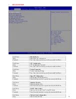
Page 26: ...26 MITAC Desktop Board PH11CMI BIOS Specification ...
Page 27: ...27 1 MAIN PAGE ...
Page 45: ...45 System Memory 1 16 1 26V ...
Page 53: ...53 4 1 HDD SECURITY ...

