


Page 2 - 8
Save manual for future reference.
FIGURE 4 -
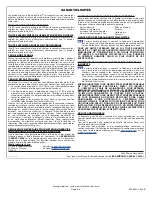
DRYWALL FINISHING
FIGURE 3B
SHIM
STUD
FIGURE 3 -
FASTENING WITH DRYWALL SCREWS
Remove the protective film from the tile flange before fastening.
FIGURE 3A
FIGURE 10
FIGURE 9
Apply silicone
caulking
FIGURE 8
FIGURE 5
FIGURE 7
FIGURE 6
SILICONE
FIGURE 11
FIGURE 12
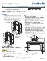
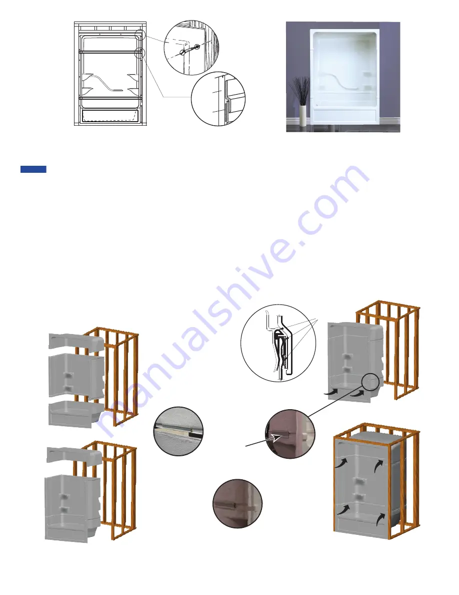
SNAP-FIT SYSTEM ASSEMBLY INSTRUCTIONS
To the Installer - Please remove all the shims from the Snap Fit extrusions of the unit prior to installation.
1. The Parker Tub Shower should be pre-assembled first prior to alcove installation. Pre assemble the unit as close to the framing as possible to
minimize movement of the unit during installation. Assemble the unit by first placing the tub section in position, followed by the mid section
and then the canopy.
2. Position the tub section first as shown in Figure 5.
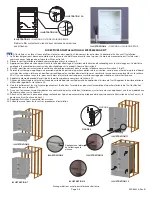
3. Apply the mildew resistant bathroom silicone caulking inside the snap fit extrusion throughout the entire length. This has to be applied to all six
snap fit extrusions on the product. See Figure 6.
4. Next, snap position the middle section carefully into the tub section. See Figures 7, 8 & 9.
5. Lock the system by applying moderate pressure from the upper portion of the mid-section, lock with the back snap first then followed by the
two side snaps . When in locked position the two sections should align and fill the gap as shown in Figure 10. If there is a gap at the seam, then
unlock and adjust the section to ensure centering to minimize the gap.
6. Repeat the same procedure to put the canopy or the upper portion in place. See Figure 11.
7. A bead of mildew resistant bathroom silicone caulking should be applied to the back side of the top and bottom joint to form a moisture
barrier. See Figure 10.
8. When fully assembled, carefully slide the unit into the frame by pushing the assembly at the bottom on the threshold. See arrows in Figure 11.
9. Should gaps be visible at top and or bottom seams, adjust the area by applying moderate force at the arrows shown in Figure 12.
10. Fasten the unit into the framed alcove by the recessed 2” x 2” around the periphery of the opening as illustrated in Figure 3, (2 vertical studs
and 1 across the top).
11. Drywall finish the framed alcove as shown in Figure 4.
12. Follow the manual for all other installation procedures.
NOTICE
R0084314, Rev B