T
A
D
K
L
C
t
r
a
h
C
n
u
R
e
r
i
W
s
u
B
-
r
u
c
e
S
2
e
l
b
a
T
G
W
A
6
1
G
W
A
8
1
t
n
e
r
r
u
C
s
r
e
t
e
M
t
e
e
F
s
r
e
t
e
M
t
e
e
F
A
m
g
n
i
m
m
a
r
g
o
r
P
s
s
e
r
d
d
A
1
e
l
b
a
T
8
9
0
3
0
6
1
0
1
4
5
9
1
0
1
4
6
5
1
s
s
e
r
d
d
A
2
J
1
J
9
4
5
1
0
8
0
5
6
7
9
0
0
2
3
0
3
2
3
0
1
5
8
3
3
1
5
6
5
3
1
2
5
4
1
F
F
O
F
F
O
4
7
7
0
4
5
2
8
8
4
0
0
6
1
0
6
2
F
F
O
N
O
9
1
6
0
3
0
2
0
9
3
0
8
2
1
5
7
3
N
O
F
F
O
5
1
5
0
9
6
1
5
2
3
5
6
0
1
0
9
4
N
O
N
O
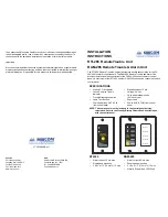
Typical wiring connections. Refer to the FA-262/265 Series
Control Panel
Installation Manual
for Secur-Bus wiring details.
INSTALLATION
T
he RTI-265 module mounts in a single gang
outlet box. The RAM-265 mounts in a double
gang outlet box. Refer to Figures 1 & 2 and
Tables 1 & 2.
1. Configure jumpers (item 1) for desired
operating address.
2. Affix zone identification labels, if
required, on the label aligned with the
LED indicators (RAM-265 Only).
3. Route Secur-Bus™ wiring through the
outlet box. Connect the 4 wires to the ter-
minals (item 2) on the PC board.
4. Position the module in the outlet box and
secure with the screws (item 3) pro-
vided (2 screws for the RTI-265, 4
screws for the RAM-265).
5. Secure the front panel (item 4) to module
with the screws provided (item 5).
OPERATION
The AC and Trouble LEDs on the remote
units follow the control panel AC and Trouble
LEDs. Pressing the Trouble Silence switch at
the panel or at any remote unit will silence
the trouble buzzer at the panel and all
remote units.
Zone indicators on the remote units follow
the zone indicators of the control panel. The
red LED will operate if the panel zone is pro-
grammed for ‘ALARM’ and the yellow LED
will operate if the panel zone is programmed
for ‘SUPERVISORY’.
The Lamp Test is initiated by pressing and
holding the Trouble Silence pushbutton for 1/
2 second. The LEDs will flash until the button
is released.


