1
2GIG-SMKT2-345
WIRELESS PHOTOELECTRIC
SMOKE AND TEMPERATURE
ALARM
Installation Instructions
DESCRIPTION
The 2GIG-SMKT2-345 is a photoelectric smoke alarm with a built-in transmitter
designed for use with the 2GIG-CNTRL-345 security system. When smoke is
detected, the alarm sounds a loud local alarm. Twenty seconds after the local
alarm sounds, the built-in transmitter sends a digitally coded wireless signal to
the Control Panel. The wireless signal will be repeated every 20 seconds as
long as smoke is still present.
In addition to the photoelectric detector, the unit contains an integrated fi xed
135° temperature and rate-of-rise heat sensor that will send an alarm signal
based on temperature detected.
BUILT-IN WIRELESS TRANSMITTER
The smoke alarm can send three different wireless signals to the alarm Control
Panel: alarm, low battery, and status.
Every hour, the smoke alarm sends a status transmission to the Control Panel.
The hourly signal updates the Control Panel with the smoke alarm’s condition.
By monitoring status transmissions, the Control Panel can determine that the
smoke alarm is still operational in the installation and if it has a low battery.
The Control Panel must be programmed to the transmitter’s serial
number before system testing and operation.
Refer to the Control Panel’s
instructions for details on programming.
INSTALLATION
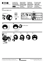
1. Slide the battery compartment cover away from the unit to unsnap it and
lift it off. See Figure 2.
2. Observing proper polarity, insert the two 3V lithium batteries supplied into
the alarm battery compartment and replace the battery cover.
3. Remove the red plastic dust cover from the unit.
4. Refer to Page 3 for selecting a proper location for the smoke alarm.
5. Using the two screws and anchors provided, mount the base.
6. Attach the unit to the base as follows:
• Line up the raised alignment tab on the lip of the unit with the alignment
arrow on the base. See Figure 3.
• Insert the unit into the base and turn clockwise approximately 15
degrees. It should snap fi rmly into place.
• IMPORTANT:
The unit cannot be attached to the base if no batteries
are installed.
PROGRAM SMOKE ALARM INTO THE CONTROL PANEL
Before testing the smoke alarm, the internal wireless transmitter must be
programmed into the Control Panel.
1. Refer to the Control Panel’s instructions to prepare the receiver to accept
the smoke alarm’s serial number.
2. Press the smoke alarm’s TEST/SILENCE button for 4 seconds. The
smoke alarm will perform a sounder test, a sensitivity test, and send a
test signal to the Control Panel.
3. Verify that the signal was received by the Control Panel and that the
sensor was entered into the system.
4. Exit Control Panel programming before testing the smoke alarm.
Technical Support 866-670-1591
www.2gig.com
388 West Center Street
Orem, UT 84057
I
R
L I S T
D
CM
Temperature
Sensor
Temperature
sensor
Test/Silence
button
Sounder vent
LED
Figure 1. Smoke Alarm Features
Battery
compartment
Figure 2. Battery Compartment
Alignment tab
Alignment arrow
Figure 3. Smoke Alarm-to-Base Alignment
SMOKE TEST
Units should be tested in place annually using one of the following methods:
A. Use Smoke! in a can
®
and follow directions on the can.
B. Hold a smoldering punk or cotton wick close to the unit and gently direct
the smoke into the smoke entry openings for 20 seconds or until an alarm
is indicated.
The smoke alarm LED should stay on and the sounder should emit a temporal
three pattern, and an alarm should be indicated at the Control Panel. Disarm
the system to reset the Control Panel alarm.
Be sure to extinguish the
smoke source after testing!
SILENCE THE ALARM
Press the TEST/SILENCE button to silence the sounder during an alarm. After
a few minutes, the sounder and alarm resume if smoke is still present.