background image

23

1079321-W2-G

OPERATION

with an adjustable maximum temperature 

setting. This must be checked and adjusted 

as necessary to suit both site conditions 

and user’s comfort.

1.

Turn  the  outer  flow  control  knob 

until  the  desired  flow  of  water  is 

obtained.  The  flow  of  water  will 

increase  the  further  the  control  is 

turned 

anticlockwise

.

2.

Turn  the  inner  temperature  control 

anticlockwise  for  warmer  water 

and  clockwise  for  cooler  water, 

the  numbers  indicate  the  relative 

temperature: 

1

 = cold, 

4

 = tepid, 

7

 = Hot 

Warning!

 Operation of the override 

button will allow a shower temperature 

above the preset maximum.

3.

To  override  the  preset  maximum 

temperature press the override button 

and turn the inner temperature control 

knob anticlockwise.

4.

clockwise

Outer Flow Control Knob

Inner Temperature Control Knob

Cooler

Warmer

Press the Override Button and turn 

the Inner Temperature Control Knob 

anticlockwise.

Outer Flow Control Knob

Off Position

For safety reasons this appliance is fitted

Turn the outer flow control knob fully

to stop the flow of water.
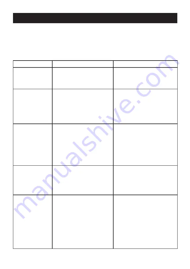
FAULT DIAGNOSIS

Fault Diagnosis - User Maintenance

The appliance is fully performance tested after assembly. Providing it has been 

unlikely event that you experience problems with your appliance then the following 

person responsible for installing your shower.

Malfunction

Cause

Remedy

Maximum 

showering 

temperature too 

hot.

Maximum temperature 

incorrectly set.

Reset maximum temperature, 

refer to 

COMMISSIONING

.

Shower 

temperature too 

cold.

Hot water cylinder 

temperature less than 12 °C 

above shower temperature.

Maximum temperature 

incorrectly set.

Adjust cylinder temperature.

Note!

 It is recommended 

stored water temperatures do 

not exceed 

65 °C

.

Reset maximum temperature, 

refer to 

COMMISSIONING

.

Blend temperature 

unstable.

Spray plate blocked.

Isolating valve partially 

closed.
Plumbing system fault.

Clean spray plate, refer to the 

instruction manual supplied 

with the 
Contact your installer.
Open valve.

Contact your installer.

Pump does not 

operate.

Electrical supply failure.
PCB or Potentiometer failure.
Motor overheated, thermal 

switch operated.

Contact your installer.
If the thermal switch operates 

repeatedly contact customer 

support for further advice.

Low or no water  Isolating valves closed.

Appliance sited above cold 

water storage cistern.

Plumbing system fault 

(airlock).

Open the isolating valves.
Contact your installer.
The appliance is not suitable 

for negative head installations, 

refer to 

INSTALLATION 

REQUIREMENTS

.

Contact your installer.

correctly installed and is operated as advised, difficulties should not arise. In the

procedure will enable you to undertake basic fault finding before contacting the

Inlet filters blocked.

shower fittings.

flow.

Inlet filters blocked.
Check valve fitted incorrectly.

Summary of Contents for 1.1532.327

Page 1: ...1 1079321 W2 G T h e r m o s t a t i c These instructions are to be left with the user POWER SHOWER THERMOSTATIC Installation and User Guide...

Page 2: ...nstruction concerning use of the appliance in a safe way and understand the hazards involved 2 Children shall not be allowed to play with the shower 3 Cleaning and user maintenance shall not be made b...

Page 3: ...to shower 16 Switch the shower off at the electrical isolating switch when not in use This is recommended with all electrical appliances 17 Installation of the shower must be carried out in accordanc...

Page 4: ...lectrical connections are tight and that there are no leaks 26 This appliance is intended to be permanently connected to the water mains and not connected by a hose set 27 Maximum Inlet Static Pressur...

Page 5: ...ves The thermostatic mixer incorporates a wax capsule sensing unit Designed to be surface mounted the Thermostatic Power Shower comes complete with an adjustable spray handset with three settings flex...

Page 6: ...re Control Knob 1 x Temperature Indicator Trim 3 x Rubber Feet 1 x Push Fit Release Tool 3 x Rubber Wall Plugs 3 x Fixing Screws Tick the appropriate boxes to familiarise yourself with the part names...

Page 7: ...7 1079321 W2 G DIMENSIONS All dimensions are nominal and in millimetres 310 66 28 210 28 20 20 130 80 88...

Page 8: ...ust be at least 12 C above the blend temperature for shut down to seepage to occur The showering temperature will be maintained to within 1 5 C of the selected showering temperature when the pressure...

Page 9: ...avity Fed system The shower MUST be fed from a cold water cistern and hot water cylinder providing nominally equal pressure INSTALLATION REQUIREMENTS 10 m Maximum 80 mm Minimum 30 60 1 5 m Max Head Ho...

Page 10: ...ny wall or cavity or tiled up to as this prevents air circulating to the rear of the unit 9 If pipework and or electrical cables enter the shower from the rear through a hole in the wall provision mus...

Page 11: ...heat transfer may damage plastic components 5 Do not use jointing compounds on the shower unit joints they may cause damage to the mechanism inside 6 Do not insert fingers into the push fit connectio...

Page 12: ...hower tray spillover level of 25 mm 2 Hot and cold inlet supply connections are Hot Left Cold Right Run the hot and cold water supply pipes at 28 mm centres make sure that the pipe ends project 30 mm...

Page 13: ...30 mm of outer cable insulation 5 Loosen the three cover securing screws and remove the shower unit cover Note The cover securing screws are captive and should not be unscrewed fully from the unit cas...

Page 14: ...n wall structures 9 Use the push fit release tool to push the grey collars into the manifold to release the shower unit from the supply pipes Warning Make sure there are no buried cables or pipes near...

Page 15: ...e inside of the unit 13 Fit the blanking plates to the unit case in the following manner For Top Inlet Pipework For Rear Inlet Pipework For Bottom Inlet Pipework Rubber Feet Fit the full blanking plat...

Page 16: ...either the wall screws supplied or alternative fixings depending on the wall structure Do not over tighten Make sure that the electrical supply cable is correctly seated in the channel in the back of...

Page 17: ...thermostatic shower will now require commissioning refer to COMMISSIONING 23 instruction manual supplied with the Refit the unit cover and secure with Insert the flow control knob in the OFF Install t...

Page 18: ...e outer flow control anticlockwise 5 Rotate the inner temperature control anticlockwise to check the hot supply and clockwise to check the cold supply 6 clockwise to the OFF position 7 T h e s h o w e...

Page 19: ...Do not depress the override button 3 Check the shower temperature 4 If the maximum temperature requires adjustment then remove the outer control knobs Slide the end of the flow control lever the outer...

Page 20: ...b with the retaining screw 8 9 Insert the temperature indicator trim and the inner temperature control knob Caution If resistance is felt when turning the inner temperature control knob DO NOT USE FOR...

Page 21: ...trim and carefully remove the override button 4 Rotate the override button through temperature indicator trim 5 the off position 6 Insert the temperature indicator trim and the inner temperature cont...

Page 22: ...oler water the numbers indicate the relative temperature 1 cold 4 tepid 7 Hot Warning Operation of the override button will allow a shower temperature above the preset maximum 3 To override the preset...

Page 23: ...losed Plumbing system fault Clean spray plate refer to the instruction manual supplied with the Contact your installer Open valve Contact your installer Pump does not operate Electrical supply failure...

Page 24: ...l after a short time 1 2 minutes then Air entering the hot pipework Refer to the plumbing system diagram in the INSTALLATION REQUIREMENTS for the correct connection method Flow of water virtually stop...

Page 25: ...re PCB failure Potentiometer failure Motor overheated thermal switch operated Check the power supply Renew the PCB Renew the harness assembly If the thermal switch operates repeatedly contact customer...

Page 26: ...age that could reduce the flow Many household and commercial cleaners including hand and surface cleaning wipes contain abrasive and chemical substances that can damage plastics plating and printing a...

Page 27: ...bly 1532 335 Cover Motor Pump Assembly components identified A Inlet Manifold Assembly components identified B Harness Assembly Concentric components identified C Solenoid Valve Assembly components id...

Page 28: ...28 1079321 W2 G 147 67 453 01 453 14 A B H A D E D E B D 1532 332 453 28 A F A E G E B E F E C C G H G H G 453 08 1532 335...

Page 29: ...when not in use Maximum User Weight 150 kg 23 5 stone Note Must be installed onto a solid wall Double Outlet Check Valve DCV H Chrome 1 0 110 55 1 An outlet double check valve designed to prevent the...

Page 30: ...30 1079321 W2 G NOTES...

Page 31: ...31 1079321 W2 G NOTES...

Page 32: ...Cromwell Road Cheltenham Gloucestershire GL52 5EP 14648 Guarantee Your product has the benefit of our manufacturer s guarantee which starts from the date of purchase This guarantee only applies in the...

Reviews: