


4
ASSEMBL
ASSEMBL
ASSEMBL
ASSEMBL
ASSEMBLY
Y
Y
Y
Y INSTRUCTIONS
INSTRUCTIONS
INSTRUCTIONS
INSTRUCTIONS
INSTRUCTIONS
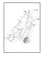
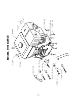
ASSEMBLING DEFLECTOR CONTROL ROD HC MODEL
ASSEMBLING DEFLECTOR CONTROL ROD HC MODEL
ASSEMBLING DEFLECTOR CONTROL ROD HC MODEL
ASSEMBLING DEFLECTOR CONTROL ROD HC MODEL
ASSEMBLING DEFLECTOR CONTROL ROD HC MODEL
1. Remove the contour head bolt (23) lockwasher (26)
and hex nut (27) from lower end of upper control
rod (10).
2. Place lower end of upper control rod (10) down
through hole in bracket (9) on upper cross bar (5).
3. Lift free end of lower control rod (11) and place inside
lower end of upper control rod (10). Align holes and
reassemble hardware from Step 1.
OPERA
OPERA
OPERA
OPERA
OPERATION
TION
TION
TION
TION AND MAINTENANCE INSTRUCTIONS
AND MAINTENANCE INSTRUCTIONS
AND MAINTENANCE INSTRUCTIONS
AND MAINTENANCE INSTRUCTIONS
AND MAINTENANCE INSTRUCTIONS
WARNING: The engine contains no oil when shipped. Read the Engine Instruction Manual and add the
proper type and amount of oil and gas before starting engine.
1. Read engine manual carefully. Be sure to know how to start
and stop engine operating unit.
2. The unit is designed to operate at full throttle, and will work
effectively by either pushing or pulling.
3. To clean an area, start at the outer perimeter and blow the
material toward the center.
4. When cleaning large areas or if debris is very dense, it may
be best to split the area into smaller plots and blow the material
into several small piles rather than one large one. As the area
being cleaned becomes smaller, reduce the engine speed to
prevent blowing the collected debris into the area already
cleaned.
HC MODELS ONL
HC MODELS ONL
HC MODELS ONL
HC MODELS ONL
HC MODELS ONLY
Y
Y
Y
Y
5. The blower housing can be adjusted to the “Hi” or “Low”
blowing position depending on the job being performed.
6. Place the blower housing in the “Low Blow” position with the
exhaust deflector straight out from side of unit for blowing dry
leaves and other light debris.
7. For blowing heavier debris such as wet leaves, twigs and
small sticks, place blower housing in “Low Blow” position with
exhaust deflector aimed downward.
8. Place the blower housing in the “Hi Blow” position for stacking
leaves in piles or windrows. The exhaust deflector should be
adjusted to achieve desired effect.
ADJUSTING BLOWER HOUSING “HI or LOW”
ADJUSTING BLOWER HOUSING “HI or LOW”
ADJUSTING BLOWER HOUSING “HI or LOW”
ADJUSTING BLOWER HOUSING “HI or LOW”
ADJUSTING BLOWER HOUSING “HI or LOW”
CAUTION: When adjusting blower housing, engine
must be shut off and spark plug wire disconnected.
1. Loosen adjusting knob, do not remove, that holds
clamp against pivot ring of blower housing.
2. Pivot blower housing to desired position and tighten
adjusting knob.
NOTE: It is not necessary to detach the deflector
control rod assembly.
3. It is possible to control the air flow from the
operating position. Turn exhaust control lever to
change deflection on angle of exhaust deflector.


