background image

CHAPTER 7  

BRUSH SYSTEM

•The significant maintenance/replacement procedures relating to the Brush 
system are described in this chapter. 
•In addition troubleshooting is described in the final section.

7.1 CLEANING DISC BRUSHES

CAUTION! The use of work gloves is 

recommended when cleaning the disc brush, due to the 
possible presence of sharp debris.

1

Remove the disc brush (See the procedure in the User and Maintenance

1.

Remove the disc brush (See the procedure in the User and Maintenance 
Manual ).

2.

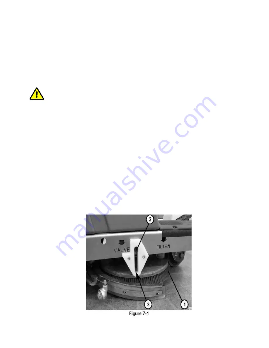
Wash and clean the disc brush (1, 

Figure 7-1

) of dirt and debris; use 

water and detergent solution.

3.

Fit the disc brush (See the procedure in the User and Maintenance 
Manual ).

Manual ).

4.

The disc brush must be replaced due to excessive wear, when in the  
condition of brush lowered, the side pins (2, 

Figure 7-1

) rest on the lower 

ends (3) of the slots.

Summary of Contents for ERide 21

Page 1: ...SERVICE MANUAL For the ERide 21 Micro Rider For Training Troubleshooting Adj t t Adjustments Rev 06 2016 ...

Page 2: ...CE 4 1 SCHEDULED MAINTENANCE PLAN CHAPTER 5 CLEANING SOLUTION 5 1 TANK CLEANING CLEANING SOLUTION 5 2 CLEANING SOLUTION FILTER 5 3 DISASSEMBLY ASSEMBLY SOLUTION FILTER 5 4 REMOVAL INSTALLATION SOLUTION PUMP 5 5 CLEANING SPRAY NOZZLE ON DISK BRUSH DECKS 5 6 CLEANING SPRAY NOZZLE ON CYLINDRINCAL BRUSH DECKS 5 7 TROUBLE SHOOTING CHAPTER 6 CHEMICAL MIXING SYSTEM 6 1 CLEANING CHEMICAL TANK VALVE 6 1 CL...

Page 3: ...DURE TO CHANGE THE MAXIMUM DRIVE SPEED OF THE 9 1 PROCEDURE TO CHANGE THE MAXIMUM DRIVE SPEED OF THE MACHINE 9 2 DISASSEMBLY ASSEMBLY OF THE DRIVE WHEEL 9 3 DISASSEMBLY ASSEMBLY OF THE DRIVE CHAIN 9 4 DRIVE MOTOR ELECTRICAL ABSORPTION CHECK 9 5 CHECK AND REPLACEMENT OF DRIVE MOTOR CARBON BRUSHES 9 6 DISASSEMBLY ASSEMBLY OF THE DRIVE MOTOR 9 6 DISASSEMBLY ASSEMBLY OF THE DRIVE MOTOR 9 7 DISASSEMBLY...

Page 4: ...DISASSEMBLY ASSEMBLY 11 3 ADJUSTING THE MACHINE FOR DIFFERENT BATTERY TYPES 11 4 CHECKING REPLACING FUSES 11 5 DISASSEMBLY ASSEMBLY DRIVE ELECTRONIC BOARD 11 6 DISASSEMBLY ASSEMBLY FUNCTIONS ELECTRONIC BOARD 11 7 REPLACING THE KEY SWITCH 11 8 TROUBLESHOOTING 11 8 TROUBLESHOOTING 11 9 ALARM CODES 11 10 WIRING DIAGRAM 12 RELAYS 13 NOTES ...

Page 5: ...the operator in the driving position on the seat 12 Figure 3 4 1 2 LIFTING THE MACHINE WARNING Do not work under the raised machine without adequate fixed safety supports 1 3 TRANSPORTING THE MACHINE WARNING Before transporting the machine with a means of transport make sure that All the doors and flaps are closed The ignition key is turned off on the control panel The machine is properly secured ...

Page 6: ...ut any operation 2 2 GENERAL INSTRUCTIONS Specific cautions and warnings are described below to highlight the potential d f d t th hi d l dangers of damage to the machine and people DANGER Before carrying out any maintenance repair disconnect the battery using the special connector This machine should only be used by properly trained and authorized personnel personnel Do not operate this machine i...

Page 7: ...ed the ignition key Do not use the machine in particularly dusty environments Do not use the machine on ramps or inclinations greater than 6 Do not knock shelves or scaffolding especially if there is a danger of falling objects Do not let any object penetrate the openings of the machine Do not use the machine if the openings are blocked keep the openings of the machine free of machine if the openi...

Page 8: ... as indicated on the machine s registration plate match the mains voltage Do not charge the batteries if the power cord or plug are damaged Do not smoke when charging the batteries To reduce the risk of fire electric shock or injury do not leave the machine connected to the mains when unattended Disconnect the machine from the socket when not being used and before maintenance Do not use the batter...

Page 9: ...riously damage the machine Only use the brushes supplied with the machine and those specified Only use the brushes supplied with the machine and those specified in User Manuals The use of other brushes can compromise your safety If lead batteries WET are installed in the machine do not tilt the machine beyond 30 horizontally so that the highly corrosive liquid in machine beyond 30 horizontally so ...

Page 10: ...mq h 2120 mq h Estimated hourly yield 1270 mq h 1270 mq h Autonomy 2 30 h 2 30 h MIT Injection Technology Yes Yes MIT capacity 0 4 3 8 L min 0 4 3 8 L min MCS Chemical System Optional Optional MCS Chemical System Optional Optional MCS ratio 1 5 1 5 Width of machine passage 65 cm 65 cm Machine body dimensions with squeegee and brush length height width 1200 x 1130 x 600 mm 1200 x 1130 x 600 mm Mach...

Page 11: ...the disc brush or cylindrical brushes 13 Light indication of the disc brush or cylindrical brushes enabled the light indication flashes when moving from enabled to disabled and vice versa 14 B tton for acti ating the lo ering of the sq eegee and the ater reco er ac m 14 Button for activating the lowering of the squeegee and the water recovery vacuum 15 Light indication of squeegee and vacuum activ...

Page 12: ......

Page 13: ...for detergent tank 14 Cap for detergent tank 15 Cap for the detergent solution or washing water 16 Recovery water drain hose 17 Detergent solution drain hose or washing water 18 Battery holder drum 19 Fl hi li ht ti l 19 Flashing light optional 20 Drink holder container only usable if the flashing light is not installed 21 Storage container only usable if the detergent tank is not installed 22 Pro...

Page 14: ...Figure 3 2 ...

Page 15: ......

Page 16: ......

Page 17: ......

Page 18: ...R FOR THE DETERGENT SOLUTION OR WASHING WATER 1 Make sure that the machine cannot move independently 2 Operating on the machine s controls as provided for in the User and Maintenance Manual lower the squeegee and the disc brush or cylindrical brushes then turn the ignition key to 0 and take it out 3 Locate the solution shut off valve on the right side of the machine and turn off 1 Figure 5 1 for t...

Page 19: ......

Page 20: ...ush then turn the ignition key to 0 off and take it out turn the ignition key to 0 off and take it out 3 Operating on the right side of the machine close the tap 1 Figure 5 2 for the detergent solution flow or washing water 4 Loosen the straps 2 and disconnect the pipes 3 from the filter unit 4 5 Unscrew the screws with nut 5 6 Remove the filter unit 4 7 If necessary break the filter unit 4 7 If n...

Page 21: ...ove the battery holder drum and disconnect the battery connector 6 Figure 3 4 For the procedure User and Maintenance Manual 2 Operating on the right side of the machine close the tap 1 Figure 5 3 for p g g p g the detergent solution flow or washing water 3 Operating on the front left side of the machine loosen the straps 2 and disconnect the pipes 3 from the pump 4 4 R th li t 5 b l i th dh i f 4 ...

Page 22: ......

Page 23: ...osition 0 4 Locate the nozzle in the center 4 Locate the nozzle in the center of the brush hub 1 Figure 5 4 unscrew the nut 2 and retrieve the nozzle 3 and the seal 4 5 Remove the filter from the housing 5 6 Clean the nozzle 3 and the filter 5 7 Correctly reposition the filter 5 in its housing in its housing 8 Position the nozzle in the housing 3 and the seal 4 then screw the ring nut 2 9 If posit...

Page 24: ...3 f f 3 Locate the spray nozzle in the front of the cylindrical brush head head unscrew the ring nut 1 Figure 5 5 and recover the nozzle 2 and the seal 3 4 Remove the filter from the housing 4 5 Clean the nozzle 2 and the filter 4 6 Correctly reposition the filter 4 in its housing 6 Correctly reposition the filter 4 in its housing 7 Position the nozzle in the housing 2 and the seal 3 then screw th...

Page 25: ...nd washing water mixing system The last paragraph also describes Troubleshooting 6 1 CLEANING THE CHEMICAL TANK AND THE CORRESPONDING VALVE VALVE 1 Make sure that the machine cannot move independently and then turn the ignition key to 0 off and remove the key 2 Remove the detergent tank from the machine 1 Figure 6 1 by gripping its handle 2 and lifting 3 3 f 3 Unscrew the cap 3 and drain the washi...

Page 26: ......

Page 27: ... Manual 4 Operating on the tank housing compartment 1 Figure 6 2 disconnect p g g p g the electrical connections 2 from the pump 3 5 Release the retaining straps 4 and disconnect the pipes 5 from the pump 6 U th 6 d th 3 6 Unscrew the screws 6 and remove the pump 3 7 If necessary remove the straps 7 and disconnect the unidirectional valve 8 from the corresponding Assembly Assembly 8 Assemble by re...

Page 28: ......

Page 29: ...it 3 Pump broken or electrical connection interrupted replace the pump restore the electrical connection the electrical connection 4 Debris in the detergent hose obstructing the passage clean the hose 5 The detergent adjustment button is inefficient check the led on the button is on otherwise change electronic board functions 6 The electronic board functions are not working replace it WATER IS ENT...

Page 30: ...ble presence of sharp debris 1 Remove the disc brush See the procedure in the User and Maintenance 1 Remove the disc brush See the procedure in the User and Maintenance Manual 2 Wash and clean the disc brush 1 Figure 7 1 of dirt and debris use water and detergent solution 3 Fit the disc brush See the procedure in the User and Maintenance Manual Manual 4 The disc brush must be replaced due to exces...

Page 31: ...s of dirt and debris use water and detergent solution 3 Also wash and clean the housings 1 Figure 7 2 of the cylindrical brushes 4 Check that the hubs 2 driving the cylindrical brushes are free of debris dirt or intertwined objects cords etc dirt or intertwined objects cords etc 5 Reassemble the cylindrical brushes See the procedure in the User and Maintenance Manual 6 The cylindrical brushes must...

Page 32: ...nition key 2 Figure 3 2 in the position 0 the ignition key 2 Figure 3 2 in the position 0 5 Remove the battery holder drum and disconnect the battery connector 6 Figure 3 4 For the procedure see the User and Maintenance Manual 6 Operating on both sides of the machine unscrew the 1 Figure 7 4 7 Unscrew the screw with nut 2 Figure 7 5 securing the actuator to the head 8 Disconnect the electrical con...

Page 33: ...he seat of the machine WARNING Do not touch any electrical components that are not protected by the panel 6 Figure 7 6 as removed 8 Turn the ignition key to I and wait for the word READY on the display 9 Operating on the machine s controls as indicated in the User and Maintenance p g Manual lower and rotate the disc brush and then check on current clamp that the absorption of the motor is approxim...

Page 34: ......

Page 35: ...ure 7 9 and remove the brush holder hub 2 5 Disconnect the tensioning spring 2 Figure 7 10 from the stud 3 5 Disconnect the tensioning spring 2 Figure 7 10 from the stud 3 6 Unscrew the screw 4 and remove the tensioner 5 7 Unscrew the screws 6 Figure 7 10 and remove the motor 7 from the disc brush Assembly 8 Assemble by reversing the sequence of operations performed for disassembly with the follow...

Page 36: ...ent contact with the armature of the motor is not provided because of their consumption the non integrity of the contact surfaces broken thrust spring etc The minimum length of the carbons 5 is 15 mm which when reached must be replaced 5 If necessary disconnect the connections 6 and remove the carbons complete with support 1 to replace them The carbons should be replaced complete with support 1 to...

Page 37: ...hub 1 Assembly 4 By means of a clamp disconnect the end 5 of the tensioning spring 6 from the stud 7 5 Insert the belt in the housing 2 making it engage the pulleys 3 and 4 and to the brush holder hub 1 and to the brush holder hub 1 6 By means of a clamp on the end 5 pull the tensioning spring 6 and make it engage with the stud 7 7 Check the efficiency of the tensioner and then manually turn the b...

Page 38: ...isconnect the battery connector 6 Figure 3 4 For the procedure see the User and Maintenance Manual 5 Operating above the brush head 1 Figure 7 11 unscrew the nut 2 6 and remove the lower retaining screw 3 of the actuator to the brush head head 6 Open the tank covers 11 Figure 3 2 and remove the panel 22 by lifting it up Lower the cover back down 11 7 Unscrew the screws 4 Figure 7 12 securing the s...

Page 39: ......

Page 40: ...e worn carbons replace the electric motor carbons 4 Faulty brush relay replace if defective 5 Electric motor in the event of a failure repair or replace the electric motor 6 El t i b d f ti d d l it if d f ti 6 Electronic board functions damaged replace it if defective 7 Damaged wiring repair it THE BRUSH DOES NOT REACH THE RAISED or LOWERED POSITION Possible causes can be 1 Electric actuator to r...

Page 41: ...ing release the bend 13 by draining the dirty water from the tank in the drain area 5 By means of the grip 4 lift the tank covers 5 6 Remove the grate 10 by lifting it then get rid of any debris and wash it 6 Remove the grate 10 by lifting it then get rid of any debris and wash it 7 Remove the grate 11 by lifting it then get rid of any debris and wash it Particularly clean the lower hole 12 8 Wash...

Page 42: ......

Page 43: ... then check on current clamp that the absorption of the vacuum motor is approximately 20 amps at 24 current clamp that the absorption of the vacuum motor is approximately 20 amps at 24 volts 7 Lift the squeegee and the disc brush 8 Turn the ignition key to the 0 9 Remove the current clamp 10 If the absorption is greater perform the steps below in sequence to locate and eliminate the cause of the a...

Page 44: ... electrical connections 4 5 Remove the carbons 5 5 Remove the carbons 5 6 Check the state of wear of the carbons which ones are worn when sufficient contact with the armature of the motor is not provided because of their consumption the non integrity of the contact surfaces broken thrust spring etc 7 If necessary replace the carbons The carbons should be replaced y p p together 8 For the reassembl...

Page 45: ...t 3 Remove the battery holder drum and disconnect the battery connector 6 Figure 3 4 For the procedure see the User and M i t M l Maintenance Manual 4 Operating on the left side of the machine unscrew the screws 1 Figure 8 4 5 Remove the support unit with the vacuum motor and filter 2 after you have disconnected the electrical connector 3 of the after you have disconnected the electrical connector...

Page 46: ......

Page 47: ...debris 1 Remove the squeegee See the procedure in the specific paragraph 2 Wash and clean the squeegee 1 Figure 8 5 in particular clean dirt and debris from the compartments 2 and the hole 3 Check that the front blade 4 and the rear blade 5 are undamaged and have no cuts or tears otherwise replace them see the procedure below 3 Refit the squeegee See the procedure in the specific paragraph ...

Page 48: ...ndamaged Even if the other three corners are worn replace the blade by operating as described below Replace or invert the rear blade 2 after having disengaged the retainer 4 released the eccentric 5 and removed the retainer strip 7 disengaging them from the pins with nut 6 finally put the blade back operating in the reverse order of removal Replace the front blade 1 after having unscrewing the nut...

Page 49: ......

Page 50: ... required when the machine does not dry properly leaving streaks of water in the central region or on the ends 8 To adjust the height of the squeegee loosen the nuts 1 Fig re 8 7 and adj st the height of the right and left heel 1 Figure 8 7 and adjust the height of the right and left wheel 2 9 At the end of the adjustment tighten the nuts ...

Page 51: ...rom the other parts of the unit the other parts of the unit 3 Clean the vacuum filter with brush and compressed air max 5 Bar If the filter is damaged replace it WARNING Adequately protecting parts of the body eyes hair hands etc when performing cleaning Operations using compressed air guns p g p g Assembly 4 Reassemble by reversing the sequence of operations performed for disassembly for disassem...

Page 52: ...e actuator rod 4 5 Operating on the machine s controls as instructed in the User and Maintenance Manual operate the squeegee s lift control so as to raise the rod 4 to facilitate the subsequent removal of the actuator Turn the ignition key to the facilitate the subsequent removal of the actuator Turn the ignition key to the 0 and take it out 6 Remove the batteries from the machine See procedure in...

Page 53: ... 2 incorrectly positioned position it correctly 2 Seal of the cover for the tanks not efficient eliminate the causes 3 Squeegee or vacuum hose clogged or damaged clean or repair replace them 4 Squeegee blades flaps torn or worn replace them THE SQUEEGEE LEAVES MARKS OR DOES NOT COLLECT WATER Possible causes can be 1 Debris under the edge of the squeegee blades remove it 2 Squeegee blades flaps tor...

Page 54: ...king into account the experience of the operator to whom the machine is entrusted for the washing drying activity The operator is absolutely prohibited from varying the maximum speed of the machine 1 Turn the ignition key to I while holding down the button 1 Figure 9 1 and wait for the display 2 the setting 3 and then release the button 1 The value 4 indicates the maximum pre set speed on the mach...

Page 55: ......

Page 56: ...igh enough to lift the front wheel by 5 of the machine high enough to lift the front wheel by 5 6 cm space necessary to then be able to remove the front wheel 5 Unscrew the nut 3 and remove the retaining screw 4 for the front wheel 6 Remove the spacers 5 and 6 7 Remove the front wheel assembly 7 by releasing the pinion 8 from the chain 9 Assembly 8 Assemble by reversing the sequence of operations ...

Page 57: ... 2 Unscrew the screw 1 Figure 9 3 and retrieve the washers 3 Remove the pinion 2 and retrieve the lug 3 4 Retrieve the self lubricating bearing 4 5 Retrie e the chain 5 5 Retrieve the chain 5 Assembly 6 Assemble by reversing the sequence of operations performed for disassembly CAUTION Do not lubricate the chain 5 in order to prevent dust and debris from mixing with the lubricant ...

Page 58: ...d reach the maximum speed corresponding to the five lights on the control panel then check on current clamp that the absorption of the drive motor is i t l 5 t 24 lt approximately 5 amps at 24 volts 9 Stop the drive by releasing the accelerator pedal 8 10 Turn the ignition key to the 0 11 Get off the machine and remove the current clamp 12 If the absorption is greater perform the steps below in se...

Page 59: ......

Page 60: ...ft the retaining clip 3 and extract the carbons 4 carbons 4 4 Check the state of wear of the four carbons the carbons are worn when sufficient contact with the armature of the motor is not provided because of their consumption the non integrity of the contact surfaces broken thrust spring etc Replacement 5 If necessary remove the carbons to replace them after having unscrewing the nuts D and freed...

Page 61: ...tery connector 6 Figure 3 4 For the procedure see the User and Maintenance Manual 4 Open the cover 1 Figure 9 6 and remove the panel 2 by lifting it up Lower the cover back down 1 5 Disconnect the electrical connections 3 of the drive motor from the drive electronic board 6 Unscrew the retaining screws 4 for the drive motor 7 Remove the drive motor 5 7 Remove the drive motor 5 8 Assemble by revers...

Page 62: ......

Page 63: ...3 Assembly 5 Assemble by reversing the sequence of operations performed for disassembly 6 Adjust the drive pedal operating according to the following procedure CAUTION In the context of the procedure described below concerning the adjustment of the drive pedal make sure you do not vary any j p y y y other setting of the machine The machine settings are set by the manufacturer to optimize the funct...

Page 64: ...on of the water dosage 3 times the display shows SET TARGET TRACTION BOARD SET TARGET TRACTION BOARD 6 Press the button TURBO to confirm the display shows T_SET PAR 0 RESET 0 7 Press the button of the water dosage 8 times the display shows SINGLE ENDED 8 Press the button TURBO TO CONFIRM the display shows CALIBRATION STOP POS 1 2 V 9 Press the button TURBO to confirm the display shows CALIBRATION ...

Page 65: ......

Page 66: ...l components that are not protected by the panel 4 as removed 6 Loosen the nuts 5 and adjust the position of the micro switch 6 Tighten the nuts 5 7 Insert the panel in the housing 4 and then close the cover 3 8 Check the functionality of the micro switch by performing the previous points from 1 to 4 Replacing the micro switch 9 Remove the battery holder drum and disconnect the battery connector 6...

Page 67: ......

Page 68: ... or replace it 4 The voltage of the batteries has dropped excessively charge the batteries 5 The drive safety micro switch is faulty repair replace it 6 The parking brake does not turn off see the chapter on the 6 The parking brake does not turn off see the chapter on the Parking brake system 7 The drive electronic board is not working replace it 8 The electronic board functions are faulty see the...

Page 69: ...machine on a level floor Make sure that the machine cannot move independently 3 Turn the ignition key to the 0 and take it out 4 Remove the battery holder drum and disconnect the battery connector 6 Figure 3 4 For the g procedure see the User and Maintenance Manual 5 Lift the cover 1 Figure 10 1 and remove the panel 2 by lifting it up Continue with the check the following of the tightening of the ...

Page 70: ...functions 4 7 Turn the lever 5 and disconnect the electrical connector 6 from the 7 Turn the lever 5 and disconnect the electrical connector 6 from the emergency stop switch 7 8 Turn the ring nut 8 and remove the emergency stop switch 7 9 Carefully remove the keyboard 9 from support panel disengaging its adhesive surface and Maintenance Manual NOTE The removed keyboard is no longer usable ASSEMBLY...

Page 71: ......

Page 72: ...disconnect the electrical cables 3 from the electrical connector 4 of the emergency stop switch 3 Unscrew the central nut 5 of the steering wheel 6 4 Using a workshop extractor pull off the steering wheel 6 from the conical g p p g engagement with a key exerting force on the point 7 opposite the points 8 To prevent damage to the steering wheel apply force distribution shims to the areas 8 5 Retrie...

Page 73: ...e the steering wheel See the procedure in the specific paragraph 2 Unscrew the screws 1 Figure 10 4 and gently lift the steering column 2 3 Disconnect the electrical connector 3 of the ignition key and then remove The steering column 2 Assembly Assembly 4 Assemble by reversing the sequence of operations performed for disassembly ...

Page 74: ...f the machine clean the adhesive residue from the dipstick housing if necessary degrease the bonding area by means of a solvent Clean and degrease the gluing perimeter of the new dipstick to be fitted 5 Apply a uniform bead of Gelson 30430 MS Flex 445 Auto glass Repair Technicians MS polymer based sealant adhesive or equivalent without interruption to the entire gluing perimeter of the new dipstic...

Page 75: ... machine on a level floor Make sure that the machine cannot move independently 3 T th i iti k t th 0 d t k it t 3 Turn the ignition key to the 0 and take it out 4 Operating on the right side of the machine loosen the strap 1 Figure 10 6 and then disconnect the detergent solution or washing water drain hose 2 from the tank coupling 5 Remove the hose 2 from the machine Assembly 6 Assemble by reversi...

Page 76: ...ion key to the 0 and take it out 4 Operating on the left side of the machine loosen the strap well 1 Figure 10 7 and then disconnect the recovery water drain hose 2 from the tank 10 7 and then disconnect the recovery water drain hose 2 from the tank coupling If necessary to facilitate the removal of the hose from the tank open the battery drum 3 See the procedure in the User and Maintenance Manual...

Page 77: ...nect the battery connector 1 Figure 11 1 See the procedure in the User and connector 1 Figure 11 1 See the procedure in the User and Maintenance Manual 2 Disengage the blade guards of the poles 2 of the batteries 3 Disconnect the terminals from the poles 2 of the batteries and move the electrical cables 3 4 Carefully remove the batteries 4 5 Assemble by reversing the sequence of operations perform...

Page 78: ... type of batteries installed make sure you do not vary any other setting of the machine The machine settings are set by the manufacturer to optimize the functional characteristics of the machine itself and are then saved before selling the machine Changing the machine settings except those covered by this manual by anyone not authorized to do so may be lead to the revocation of the warrant of the ...

Page 79: ...RD 0 3 Press the button of the detergent dosage until you reach th b 61 the number 61 4 Press Turbo button 5 Press the button of the water dosage until the display shows SET TARGET FUNCTION BOARD 6 Press the button TURBO to confirm the display will show the type of battery the machine is set for PB24 corresponding to WET lead acid batteries GeE24 corresponding to GEL batteries Optima corresponding...

Page 80: ... and Maintenance Manual 4 Open the cover 1 Figure 11 2 and remove the panel 2 by lifting it up Lower the cover back down 1 Checking replacing fuses 10 A fuse for protecting auxiliary services 3 Figure 11 2 80 A fuse drive protection board 4 Figure 11 2 30 A fuse for vacuum motor protection 5 Figure 11 2 30 A fuse for vacuum motor protection 5 Figure 11 2 40 A fuse for brush motor protection 6 Figu...

Page 81: ...11 4 Fuses ...

Page 82: ... the cover 1 Figure 11 3 and remove the panel 2 by lifting it up Lower the cover back down 1 3 Disconnect the electrical connections 5 from the drive electronic board 4 board 4 4 Disconnect the electrical connections 5 from the drive electronic board 4 5 Unscrew the screws 6 and remove the electronic drive board 4 Assembly 6 Assemble by reversing the sequence of operations performed for disassembl...

Page 83: ... connections 5 from the functions electronic board 4 7 Turn the lever 5 and disconnect the electrical connector 6 from the emergency stop switch 7 8 R t i th k b d bl ith f ti l t i b d 2 8 Retrieve the keyboard assembly with functions electronic board 2 9 On a workbench disconnect the electrical connectors 9 for the keyboard wiring from the functions electronic board 8 of the keyboard 10 Unscrew ...

Page 84: ......

Page 85: ...ng column See the procedure in the specific paragraph 2 Operating from inside the steering column 1 Figure 11 5 loosen the lock nut 2 and remove the ignition key 3 Assembly Assembly 3 Assemble by reversing the sequence of operations performed for disassembly ...

Page 86: ...ttery Charger failure replace it only for the version with the charger in the machine 4 Interrupted fuses replace them 5 Electrical wiring cut or crushed in short circuit repair it 11 9 ALARM CODES Any active alarms on the machine are displayed using the display 3 Figure 3 1 of the control panel Alarms can relate to the functions board CFI0000 identified as Control Alarm or drive board 7CH4Q90A id...

Page 87: ...11 9 ALARM CODES ...

Page 88: ...K3 Brush release contactor M3 Chemical Pump detergent M4 Water pump M1 Brush actuator M2 Squeegee actuator BR Reverse horn SW2 Seat micro switch SW1 Ignition key switch LAMP Flashing SPEED REFERENCE D i d l t ti t SPEED REFERENCE Drive pedal potentiometer SP Brush motor ASP Vacuum motor M Drive motor F2 Blade fuse 10A auxiliary F1 Fuse midi 80 A drive F3 Fuse midi 30 A vacuum F4 Fuse midi 40A brus...

Page 89: ......

Page 90: ...12 Relays and Drive Controller ...

Page 91: ...13 Notes ...

Reviews: