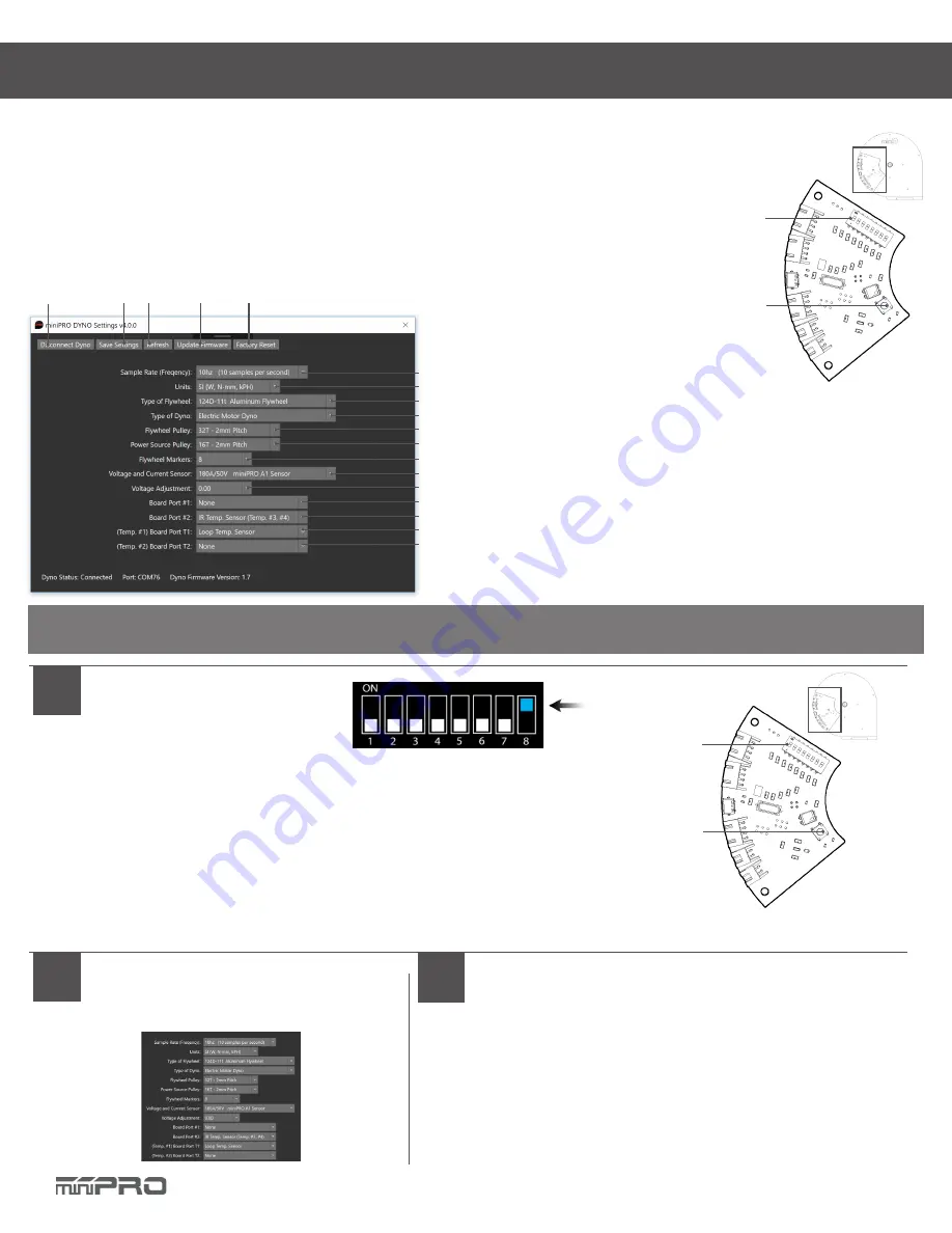
Mini Pro Chassis Dyno V1 Instruction Manual Download Page 17

16

DYNO SETUP

General Settings

SETUP MODE

7

8
9

10
11
12

14

5

4

3

2

1

5. Factory reset your dyno settings 
6. Set sample rate (Frequency)
7. Set the units of your dyno
8. Set the type of flywheel
9. Set the type of dyno
10 Set the flywheel pulley
11. Set the motor pulley (power source)
12. Number of flywheel markers (black tape on the flywheel)
13. Set the current sensor used
14. Voltage Adjustment 
15. Port #1: for LCD 
16. Port #2: for IR Temp. 
17. Port T1: for Loop Temp. Sensor (Temp #1)
18. Port T2: for Loop Temp. Sensor (Temp #2)
19. Setting Switches 
20. Reset Button

19

20

Electronic Board

To access the settings of your dyno, you must open the main application and select “ Dyno Settings.”

1

Enter Setup Mode

1.1. Open the main application
1.2. Select “Connect Dyno”
1.3. Change 

only

 Switch #8 to ON.

1.4. Press the Reset button 1-2 times on the board.
1.5. The Settings application should load automatically.
1.6. (Optional) If the settings application did not load automatically, select “Dyno Settings” 
and follow the screen instructions.

Electronic Board

Switches

Reset Button

NOTE: 

Make sure you have firmware v1.7 or later, and installed the latest application of  

miniPRO Dyno before you continue.

3

Change your Settings

4

Change your Switches

3.1. Select your desired settings
3.2 Select “Save” to complete your settings.

4.1. When finished, select “Disconnect.”
4.2. Change 

only

 Switch #8 to OFF.

4.3. Close the Settings Application.
4.4. Done! The main application should load auto-
matically.

13

15
16

17
18

6

1. Connect/Disconnect the dyno to setup mode
2. Save the settings of your dyno
3. Refresh (re-load) the settings of your dyno
4. Update Firmware Icon

Summary of Contents for Chassis Dyno V1

Page 1: ...CHASSIS DYNO V1 Instruction Manual REV2 0...

Page 2: ......

Page 3: ...struction man ual and fully understand them to get the maximum enjoyment and prevent unnecessary damage Read carefully and fully un derstand the instructions before beginning assembly Contents of the...

Page 4: ......

Page 5: ...ghlights 6 Assemble the Dyno 7 Electronic Connections 8 miniPRO Volt Current Sensor 8 Attopilot Volt Current Sensor 10 ESC Servo Controller Sensor 11 Driver Installation 12 Dyno Driver for Windows 7 8...

Page 6: ...5 Dyno Setup 16 General Settings 16 Firmware Update 17 CONTENTS...

Page 7: ...o is great tool for motor analysis ESC boost adjustment brushless sensor adjustment gearing calculation acceleration testing kV measuring voltage drop current draw power and torque output analysis May...

Page 8: ...ate and straps for the vehicle NOTE If you are using your Motor Dyno Flywheel Assy then you need to remove the belt shield and holder from the dyno Install the Flywheel Base Install the Flywheel Assy...

Page 9: ...iagram for more information 3 2 Connect the battery to the sensor s battery connector 3 3 Turn ON the ESC and make sure it powers on If the sensor starts to overheat disconnect the battery immediately...

Page 10: ...NIC CONNECTIONS Connect Transmitter Receiver and ESC to the Motor Connect Sensor Connect Sensor to Electronic Board 2 3 4 Voltage and Current Sensor Diagram Solder Connector 1 7 6 2 5 4 3 1 5 4 3 Volt...

Page 11: ...ONIC CONNECTIONS Connect Transmitter Receiver and ESC to the Motor Connect Sensor Connect Sensor to Electronic Board 2 3 4 Voltage and Current Sensor Diagram Solder Connector 1 7 6 2 5 4 3 1 5 4 3 Vol...

Page 12: ...ect the ESC s throttle OR the Servo s throttle cable to the sensor s throttle port See above sensor driagram for more OR Ground Positive Signal ESC Connection Electrical Powered Vehicles Servo Connect...

Page 13: ...er 1 2 3 1 Go to right click on Computer Click Properties 3 2 In the Properties window click on Device Manager 4 1 Select Browse my computer 4 2 Select Let me pick from a list 4 3 Select Have a disk a...

Page 14: ...ctrinic board driver is installed automatically by Windows 10 however you must update the driver NOTE The communication port is required to run the dyno Above port number may differ from your pc CONT...

Page 15: ...the steps required to install the sensor 1 2 CONT Go to http minipro wiki downloads Download the latest driver and extract the driver to a new folder During the installation Windows will ask you if yo...

Page 16: ...indows 5 6 Select the location folder where mini D will be installed and then select the person who can use the application Click Next Confirm that you want to install mini D on your computer and clic...

Page 17: ...application 1 2 Select Connect Dyno 1 3 Change only Switch 8 to ON 1 4 Press the Reset button 1 2 times on the board 1 5 The Settings application should load automatically 1 6 Optional If the settings...

Page 18: ...e your settings 3 8 Select Disconnect 3 9 Change only Switch 8 to OFF press the reset button and close the application 4 1 If the automatically factory reset from step 3 5 worked then go to step no 5...

Page 19: ......

Page 20: ......

Page 21: ...CHASSIS DYNO www minipro com 2018 miniPRO LLC All Rights Reserved...

Reviews: