


-5.19-
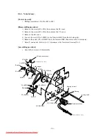
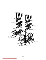
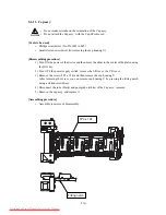
5-1-13. IEEE1394 PCB, Main PCB, HDC-4 Head PCB assy., HDC-2 Head PCB assy.
and Power PCB
[Tools to be used]
•
Phillips screwdriver (No.2 for M3 to M5)
•
Box wrench (opposite side distance: 5.5 mm)
[Disassembling procedure]
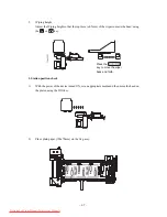
<IEEE1394 PCB>
1) Turn OFF the power supply switch, remove the electrical unit cover.
2) Remove the screw (B3 x 6Bk) and remove the IEEE1394 PCB together with connection
board.
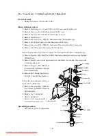
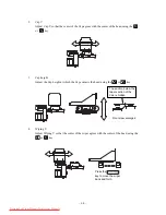
Follow the procedure given below to replace the main PCB.
1) Remove all of the cables connected to the main PCB.
2) Remove the screw (P3 x 8SMW, SQ-30, the screw for the pararell connector) and remove
the main PCB.
Follow the procedure given below to replace the power PCB.
1) Remove the screw (B3 x 6Bk, P3 x 6SMW) and remove the main PCB BKT.
2) Remove all of the cables connected to the power PCB.
3) Remove the screw (P3 x 8SMW) and remove the poser PCB.
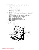
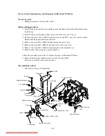
to Cover sensor assy.
to Maintenance cover sensor assy.
to Y-axis motor assy.
to Y-axis motor assy.
to X-motor junction cable assy.
to X-motor junction cable assy.
to X-origin sensor assy.
to HDC-4Head PCB assy. CN1
to HDC-2Head PCB assy. CN1
to IO PCB assy. CN1
to Keyboard PCB assy. CN2
to Power PCB assy. CN2
to Ink sensor PCB assy. CN17
to Ink sensor PCB assy. CN17
B3 x 6Bk
P3 x 8SMW
P3 x 8SMW
INK FPC1 assy.
INK FPC2 assy.
Electrical unit cover
I/F connection board assy.
1394 PCB assy.
Spacer
Downloaded From ManualsPrinter.com Manuals
Summary of Contents for JV4-130
Page 2: ...Downloaded From ManualsPrinter com Manuals ...
Page 8: ... vi Downloaded From ManualsPrinter com Manuals ...
Page 9: ... 1 1 CHAPTER 1 OVERVIEW OF MAINTENANCE Downloaded From ManualsPrinter com Manuals ...
Page 18: ... 1 10 Downloaded From ManualsPrinter com Manuals ...
Page 19: ... 2 1 CHAPTER 2 EXPLANATION OF OPERATION Downloaded From ManualsPrinter com Manuals ...
Page 23: ... 2 5 Main PCB block diagram Downloaded From ManualsPrinter com Manuals ...
Page 38: ... 2 20 Downloaded From ManualsPrinter com Manuals ...
Page 59: ... 4 1 CHAPTER 4 MAINTENANCE MODE Downloaded From ManualsPrinter com Manuals ...
Page 130: ... 4 72 Downloaded From ManualsPrinter com Manuals ...
Page 131: ... 5 1 CHAPTER 5 DISASSEMBLING ASSEMBLING PROCEDURE Downloaded From ManualsPrinter com Manuals ...
Page 152: ... 5 22 Downloaded From ManualsPrinter com Manuals ...
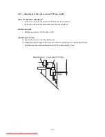
Page 153: ... 6 1 CHAPTER 6 ADJUSTMENT Downloaded From ManualsPrinter com Manuals ...
Page 154: ... 6 2 6 1 Adjusting item list Downloaded From ManualsPrinter com Manuals ...
Page 168: ... 6 16 Downloaded From ManualsPrinter com Manuals ...


