background image


THB & TLB


Oil Furnaces

 – 

Furnace Manual


670-000-005/1010  

7


2


Prepare furnace and place in position 


Blocked Vent Shut-Off (BVSO) for chimney venting 

(OPTIONAL) 

It is imperative that this device be installed by a 
qualified agency. 
 

This device is designed to detect the insufficient evacuation of 
combustion gases in the event of a vent blockage. In such a case 
the thermal switch will shut down the oil burner. The device will then 
need to be re-armed MANUALLY. 
 
In the event that the BVSO repetitively shuts down the oil burner, a 
qualified technician needs to evaluate the cause of this shut down. 
 
Refer to the figures 3 to 5 at section 6, Wiring Diagrams and detailed 
instructions supplied with the BVSO for the installation and wiring 
procedures.  
It is also essential the the BVSO be maintained annually.  
For more details refer to the instructions supplied with the device 
itself, as well as the Maintenance Section. 
 

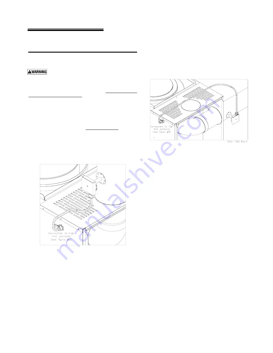
Figure 1 

Blocked Vent Shutt-Off device wiring 

Installation : Upflow with Vertical exhaust 

(Optional) 


Figure 2 

Blocked Vent Shutt-Off device wiring 

Installation : Upflow with Horizontal exhaust 

(Optional) 


Summary of Contents for THB High Boy series

Page 1: ...consignee Do not store or use gasoline or other flammable liquids or vapors near this furnace or any other appliance Ventilate house while operating furnace for the first time Odors may be emitted for a brief period Do not alter this furnace in any way The manufacturer will not be liable for any damage resulting from changes made in the field to the furnace or its components or from improper insta...

Page 2: ... the burner of furnace Installation 18 Do not block flow of combustion or ventilation air to furnace Do not block or obstruct the air openings in the furnace casing 19 Connect furnace only to a functional vent system in good condition Place the furnace to allow proper venting with the shortest possible venting and minimum number or elbows 20 Always connect and seal a return air duct to the furnace...

Page 3: ...d for installation on combustible flooring but must never be installed on carpeting Do not install furnace on carpeting even if foundation is used Fire can result causing severe personal injury death or substantial property damage Foundation 1 Provide a solid brick or minimum 2 inch concrete foundation pad if any of the following is true The floor can become flooded The furnace mounting area is no...

Page 4: ...r and fireplace When outside air is used Connect each opening directly by way of ducts to the outdoors or to crawl or attic space that freely connects with outdoors Size per below Through outside wall or vertical ducts at least 35 sq in per 1 GPH input 1sq in per 4 000 BTU input of all fuel burning appliances plus requirements for any equipment that can pull air from room including clothes dryer a...

Page 5: ...avoid Spray cans containing chloro fluorocarbons Permanent wave solutions Chlorinated waxes cleaners Chlorine based swimming pool chemicals Calcium chloride used for thawing Sodium chloride used for water softening Refrigerant leaks Paint varnish removers Hydrochloric acid muriatic acid Cements and glues Antistatic fabric softeners used in clothes dryers Chlorine type bleaches detergents and clean...

Page 6: ...ing Verify the size of the supply and return duct system is sufficient for the application The pressure drop through the duct system must not exceed 0 25 inches water column The total drop through the duct system and air conditioning condensing coil if used must not exceed 0 5 inches water column See suggested duct sizing in this manual For more detailed sizing information refer to ACCA Manual D O...

Page 7: ...Y In the event that the BVSO repetitively shuts down the oil burner a qualified technician needs to evaluate the cause of this shut down Refer to the figures 3 to 5 at section 6 Wiring Diagrams and detailed instructions supplied with the BVSO for the installation and wiring procedures It is also essential the the BVSO be maintained annually For more details refer to the instructions supplied with ...

Page 8: ... the same furnace installed with a 4 ton air conditioning evaporator coil Heating mode air flow is still 1 050 CFM Cooling mode air flow use Equation 3 4 CFM 4 x 400 1 600 CFM The larger number is 1 600 CFM cooling so the duct system should be sized for 1 600 CFM The supply duct would need to be 18 round or a rectangular equivalent such as 8 x 36 or 12 x 21 using Table 4 page 9 Always check the si...

Page 9: ... 7 7 6 6 900 14 58 41 31 25 21 19 17 14 12 11 10 9 8 8 7 7 7 1000 16 64 45 34 28 23 20 18 15 13 11 10 9 9 8 8 7 7 1100 16 72 49 38 30 25 22 19 16 14 12 11 10 9 9 8 8 7 1200 16 54 41 33 27 24 21 17 15 13 12 11 10 9 9 8 8 1300 16 58 44 35 29 25 22 18 16 14 12 11 10 10 9 9 8 1400 18 63 47 38 31 27 24 19 16 14 13 12 11 10 10 9 9 1500 18 68 51 40 34 29 25 20 17 15 14 12 12 11 10 10 9 1600 18 72 54 43 3...

Page 10: ...12 600 12 59 38 28 22 19 16 15 13 700 12 69 44 32 25 21 18 16 15 13 800 14 50 36 29 24 20 18 16 14 900 14 56 41 32 26 22 20 18 15 1000 16 63 45 35 29 24 22 19 17 15 1100 16 69 49 38 31 26 23 21 18 16 1200 16 75 53 41 33 28 25 22 19 17 1300 16 58 44 36 30 26 24 20 18 1400 18 62 47 38 32 28 25 21 18 17 1500 18 66 50 41 34 30 26 22 19 18 1600 18 71 54 43 36 31 28 23 20 18 1700 18 57 46 38 33 29 24 21...

Page 11: ...ce a minimum of inch per foot 2 Connect full sized venting when possible See Table 6 3 Connection must be made above bottom of chimney to avoid blockage Vent pipe must not enter chimney far enough to cause obstruction Use thimble or slip joint where vent pipe enters chimney to allow removal for cleaning 4 When burner and furnace are properly installed draft overfire will be approximately 0 01 to 0...

Page 12: ...isconnected before installing or servicing Wire burner The burner harness is factory wired to the furnace at the factory Plug the burner harness into the mating burner connector to wire the burner Refer to the wiring diagram on pages 14 and 15 for further information Install and wire thermostat Locate the room thermostat on an interior wall in the natural circulating path of room air Do not locate...

Page 13: ...er Figure 3 Blocked Vent Shut Off device wiring Optional Blocked Vent Shutt Off device BVSO Electrical kit supplied Connect one red wire to limit switch Disconnect red wire from limit switch and connect to one red wire from BVSO Connect the green ground wire to a cabinet screw ...

Page 14: ...THB TLB Oil Furnaces Furnace Manual 14 670 000 005 1010 6 Wire furnace burner continued Figure 4 Wiring THB TLB furnaces with direct drive blowers ...

Page 15: ...THB TLB Oil Furnaces Furnace Manual 670 000 005 1010 15 6 Wire furnace burner continued Figure 5 Wiring THB TLB furnaces with direct drive blowers ...

Page 16: ...n chamber CO2 between 10 and 11 with 0 smoke To start furnace continued Make final burner adjustments using combustion test equipment to assure proper operation 8 Check furnace and duct system for proper operation and conditions 9 Inspect vent system for proper operation 10 To set limit fan switch The blower operates until the air temperature drops below the fan OFF setting If the air at the suppl...

Page 17: ...event possible flue gas leakage and carbon monoxide emissions leading to severe personal injury or death 24 Limit control tested per To start up in this manual 25 Furnace cycled with thermostat Raise to highest setting and verify furnace goes through normal start up cycle Lower to lowest setting and verify furnace goes off 26 Observed several operating cycles for proper operation 27 Set room therm...

Page 18: ...k nozzle and electrode position Check ignition transformer output Reference burner manufacturers instructions Check tube insertion and alignment Check nozzle and electrode position Reference burner manufacturer s instructions Replace nozzle Check pump pressure varies with manufacturer and application see burner manual Check overfire draft 1 Remove CAD cell leadwires from the f f terminals on the p...

Page 19: ...n on page 20 Failure to comply could result in severe personal injury death or substantial property damage Consult with homeowner to see if there were any Check sequence of operation problems with furnace or system during the prior Check flame characteristics heating season or cooling season Perform combustion checks tests per burner manual and Clean inspect and lubricate blower motor and wheel fu...

Page 20: ...lace it in a plastic bag for disposal Wash potentially contaminated clothes separately from other clothing Rinse clothes washer thoroughly NIOSH stated First Aid Eye Irrigate immediately Breathing Fresh air HANDLING OR REMOVAL OF FIBERGLASS WOOL OR INSTALLATION OF FIBERGLASS WOOL OR COMBUSTION CHAMBER This product contains fiberglass jacket insulation and ceramic fiber materials in combustion cham...

Page 21: ...urner may need to be lubricated if motor is equipped with oiling cups Refer to burner manual for specific instructions If instructed apply a few drops only of S A E 20 detergent oil never use household oils Do not attempt to fill up the oil cup Over oiling can damage the motor Annual start up Follow information below to prevent severe personal injury death or substantial property damage Do not use...

Page 22: ...mbly cover 3 Remove the cover 4 Remove the two screws holding the thermal switch to the assembly base 5 Without removing the electrical wires remove the thermal switch and remove any build up from the thermal switch surface Do not dent or scratch the surface of the thermal switch If the thermal switch is damaged replacement is required 6 Clear and remove any build up or obstruction inside the heat...

Page 23: ...THB TLB Oil Furnaces Furnace Manual 670 000 005 1010 23 11 Components and replacement parts Figure 6 Model THB furnaces Component locations B50106A ...

Page 24: ...front panel B03057 27 Fan limit control R02I002 Front divider panel 28 Rear baffle B03062 item 9 included 29 Heat shield baffle B03060 9 Front divider insulation B03108 Blower assembly 10 Burner gasket B03071 items 31 32 33 34 36 11 Burner plate B03105 31 Blower 100 10T B03720 04 12 Hexagonal flange nut 3 8 16nc brass F07O001 32 5 MF capacitor L01I001 13 Front door B03109 33 Capacitor holder B0102...

Page 25: ...THB TLB Oil Furnaces Furnace Manual 670 000 005 1010 25 11 Components and replacement parts Figure 7 Model TLB Rear flue furnaces Component locations B50107A ...

Page 26: ...ly 9 Front divider panel insulation B03089 items 31 32 33 34 36 37 10 Burner panel B03071 31 Blower 100 10T B03720 04 11 Burner panel gasket B03105 32 5 MF capacitor L01I001 12 Hexagonal flange nut 3 8 16nc brass F07O001 33 Capacitor holder B01024 13 Front door B03085 34 Rubber cap capacitor L99Z007 14 Electrical box cover B02978 35 Electrical wire harness blower B02916 Electrical box assembly 36 ...

Page 27: ...THB TLB Oil Furnaces Furnace Manual 670 000 005 1010 27 11 Components and replacement parts Figure 8 Model TLB Front flue furnaces Components locations B50108A ...

Page 28: ...anel insulation B03086 Blower assembly 9 Burner panel gasket B03071 items 30 31 32 33 35 36 10 Burner panel B03105 30 Blower 100 10T B03720 04 11 Hexagonal flange nut 3 8 16nc brass F07O001 31 5 MF capacitor L01I001 12 Front door B03085 32 Capacitor holder B01024 13 Electrical box cover B02978 33 Rubber cap capacitor L99Z007 Electrical box assembly 34 Electrical wire harness blower B02916 items 15...

Page 29: ... 700 0 65 83 5 81 0 100 10T 1 3 Med Low Med Low 3 975 925 105 000 87 900 0 75 82 0 80 5 100 10T 1 3 Med High High 3 1100 1050 119 000 98 400 0 85 81 0 80 0 100 10T 1 3 High High 3 1225 1150 Blower CFM Direct drive units THB 105 Blower motor HP Installed nozzle Model Input Output Maximum cooling capacity Blower speed Firing rate AFUE with vent damper AFUE Blower size Maximum heating Filter Electric...

Page 30: ...W C 0 50 W C 91 000 79 100 0 65 83 5 81 0 100 10T 1 3 Med Low Med Low 3 1050 975 105 000 90 500 0 75 82 0 80 5 100 10T 1 3 Med High High 3 1150 1125 119 000 101 500 0 85 81 0 80 0 100 10T 1 3 High High 3 1300 1150 Blower speed Input Output Firing rate AFUE with vent damper AFUE Blower size Blower CFM Direct drive units TLB 105R Blower motor HP Installed nozzle Model Maximum heating Filter Electric...

Page 31: ... W C 0 50 W C 91 000 78 900 0 65 83 5 81 0 100 10T 1 3 Med Low Med Low 3 1050 975 105 000 89 300 0 75 82 0 80 5 100 10T 1 3 Med High High 3 1150 1125 119 000 99 900 0 85 81 0 80 0 100 10T 1 3 High High 3 1300 1150 Blower speed Firing rate AFUE with vent damper AFUE Blower size Blower CFM Direct drive units TLB 105F Blower motor HP Installed nozzle Model Input Output Maximum heating Filter Electric...

Page 32: ...PSIG 91 000 0 65 0 65 70A 100 105 000 0 75 0 75 70A 100 119 000 0 85 0 85 60A 100 2 1 25 2 2 25 Model Input Firing rate USGPH Nozzle Delavan THB 105 TLB 105F R Combustion air adjustment Bar Band 2 3 25 Static disc Combustion air adjustment RIELLO BURNER Model 40 F3 Tube insertion 6 1 2 Model Input Firing rate USGPH Nozzle Delavan Turbulator Band THB 105 TLB 105F R BECKETT BURNER Model AF F3 3450 R...

Page 33: ... 1120 1090 Med Low 1095 1065 1035 1005 975 945 915 Med High 1165 1155 1145 1135 1125 1090 1030 High 1360 1330 1270 1210 1150 1090 1030 Med Low 1095 1065 1035 1005 975 945 915 Med High 1165 1155 1145 1135 1125 1090 1030 High 1360 1330 1270 1210 1150 1090 1030 Notes Airflow values in cubic ft per minute CFM rounded to nearest 5 CFM Data taken with filters in place TLB 105F TLB 105R External static p...

Page 34: ...stat 2 If the furnace oil burner should shut down on flame failure the burner primary control will lock out Ask your service technician to show you the correct procedure to reset the primary control button NEVER push the button more than once in an attempt to start the burner after lockout Continued lockout of the control means something is wrong with the burner controls or oil system The conditio...

Page 35: ......

Page 36: ...THB TLB Oil Furnaces Furnace Manual X40108 Rev J ...

Reviews: