14
VIII
English
TECHNICAL DATA
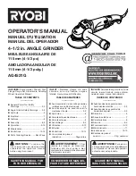
Angle Grinder
AGV 22-230
(
110-120 V)
AGV 22-230
(220-240 V)
AG 22-230 E
(
220-240 V)
AGV 22-230 E
(220-240 V)
Noise information
Measured values determined according to EN 60745. Typically, the A-weighted noise levels of the tool are:
Sound pressure level (Uncertainty K=3dB(A))
92,5 dB (A)
94,5 dB (A)
94,5 dB (A)
94,5 dB (A)
Sound power level (Uncertainty K=3dB(A))
Wear ear protectors!
103,5 dB (A)
105,5 dB (A)
105,5 dB (A)
105,5 dB (A)
Vibration information
Vibration total values (triaxial vector sum) determined according to EN 60745
Surface grinding: Vibration emission value a
h,SG
Uncertainty K=
8,3 m/s
2
1,5 m/s
2
8,3 m/s
2
1,5 m/s
2
8,5 m/s
2
1,5 m/s
2
8,3 m/s
2
1,5 m/s
2
Disk sanding: Vibration emission value a
h,DS
Uncertainty K=
3,7 m/s
2
1,5 m/s
2
3,7 m/s
2
1,5 m/s
2
3,9 m/s
2
1,5 m/s
2
3,7 m/s
2
1,5 m/s
2
For other applications, e.g. Abrasive Cutting-Off Operations or Wire Brushing other vibration values could occur.
WARNING!
The vibration emission level given in this information sheet has been measured in accordance with a standardised test given in EN 60745
and may be used to compare one tool with another. It may be used for a preliminary assessment of exposure.
The declared vibration emission level represents the main applications of the tool. However if the tool is used for different applications,
with different accessories or poorly maintained, the vibration emission may differ. This may significantly increase the exposure level over
the total working period.
An estimation of the level of exposure to vibration should also take into account the times when the tool is switched off or when it is
running but not actually doing the job. This may significantly reduce the exposure level over the total working period.
Identify additional safety measures to protect the operator from the effects of vibration such as: maintain the tool and the accessories,
keep the hands warm, organisation of work patterns.
WARNING!
Read all safety warnings and all instructions.
Failure to
follow the warnings and instructions may result in electric shock,
fire and/or serious injury.
Save all warnings and instructions for future reference.
ANGLE GRINDER SAFETY WARNINGS
Safety Warnings Common for Grinding, Sanding, Wire
Brushing or Abrasive Cutting-Off Operations:
a) This power tool is intended to function as a grinder,
sander, wire brush or cut-off tool. Read all safety warnings,
instructions, illustrations and specifications provided with
this power tool.
Failure to follow all instructions listed below may
result in electric shock, fire and/or serious injury.
b) Operations such as polishing are not recommended
to be performed with this power tool.
Operations for which
the power tool was not designed may create a hazard and cause
personal injury.
c) Do not use accessories which are not specifically
designed and recommended by the tool manufacturer.
Just
because the accessory can be attached to your power tool, it does
not assure safe operation.
d) The rated speed of the accessory must be at least equal
to the maximum speed marked on the power tool.
Accesso-
ries running faster than their rated speed can break and fly apart.
e) The outside diameter and the thickness of your
accessory must be within the capacity rating of your power
tool.
Incorrectly sized accessories cannot be adequately guarded
or controlled.
f) Threaded mounting of accessories must match the grin-
der spindle thread. For accessories mounted by flanges, the
arbour hole of the accessory must fit the locating diameter
of the flange.
Accessories that do not match the mounting hard-
ware of the power tool will run out of balance, vibrate excessively
and may cause loss of control.
g) Do not use a damaged accessory. Before each use inspect
the accessory such as abrasive wheels for chips and cracks,
backing pad for cracks, tear or excess wear, wire brush for
loose or cracked wires. If power tool or accessory is dropped,
inspect for damage or install an undamaged accessory. After
inspecting and installing an accessory, position yourself and
bystanders away from the plane of the rotating accessory
and run the power tool at maximum no-load speed for one
minute.
Damaged accessories will normally break apart during this
test time.
h) Wear personal protective equipment. Depending on ap-
plication, use face shield, safety goggles or safety glasses. As
appropriate, wear dust mask, hearing protectors, gloves and
shop apron capable of stopping small abrasive or workpiece
fragments.
The eye protection must be capable of stopping flying
debris generated by various operations. The dust mask or respirator
must be capable of filtrating particles generated by your operation.
Prolonged exposure to high intensity noise may cause hearing loss.
i) Keep bystanders a safe distance away from work area. An-
yone entering the work area must wear personal protective
equipment.
Fragments of workpiece or of a broken accessory may
fly away and cause injury beyond immediate area of operation.
j) Hold the power tool by insulated gripping surfaces only,
when performing an operation where the cutting accessory
may contact hidden wiring or its own cord.
Cutting accessory
contacting a „live“ wire may make exposed metal parts of the power
tool „live“ and could give the operator an electric shock.
k) Position the cord clear of the spinning accessory.
If you lose
control, the cord may be cut or snagged and your hand or arm may be
pulled into the spinning wheel.
Summary of Contents for 4000431861
Page 1: ...Original instructions AG 22 180 AG 22 230 AG 22 230 E AGV 22 180 E AGV 22 230 AGV 22 230 E ...
Page 3: ...2 I AG22 180 AG22 230 AG22 230 E AGV22 180 E AGV22 230 AGV22 230 E ...
Page 4: ...3 II 1 2 3 1 2 II AGV22 180 E AGV22 230 AGV22 230 E ...
Page 5: ...4 AG22 180 AG22 230 AG22 230 E II 1 3 2 2 1 ...
Page 6: ...5 III 1 30 6 0 30 6 0 0 1 A B ...
Page 7: ...6 IV Use only spindle nuts as provided by the manufacturer 1 2 ...
Page 8: ...7 IV 4 3 3 2 4 1 6 mm 6 mm ...
Page 11: ...10 TIP VI 30 TIP 30 30 ...
Page 12: ...11 1 2 1 2 VII Accessory ...
Page 13: ...12 1 2 1 2 VII Accessory ...